Quick Start Guide
Accessing Design Engine
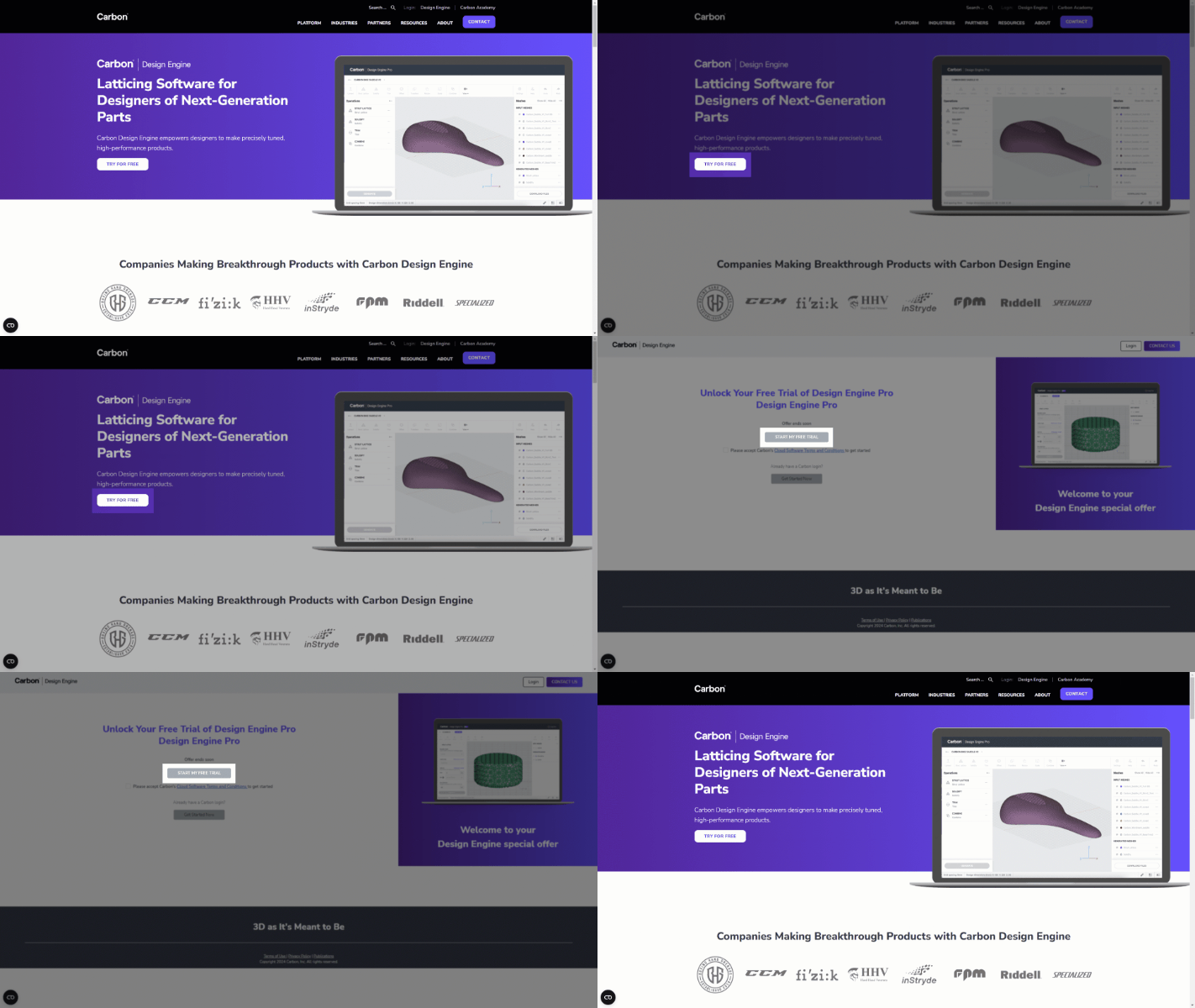
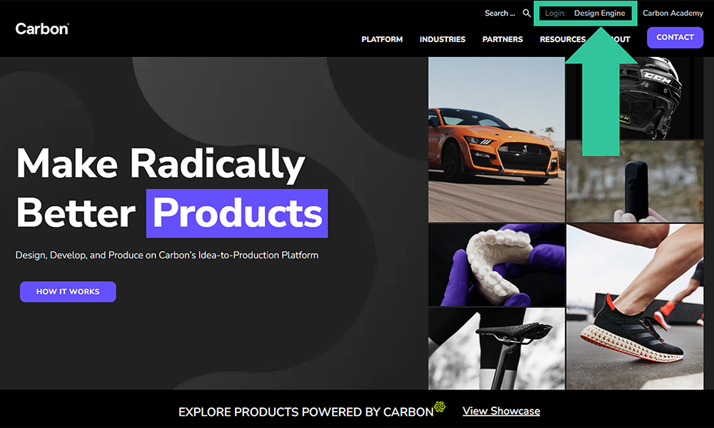
- Carbon Website | carbon3d.com A login link for Design Engine is persistent at the top of all pages on Carbon's website.
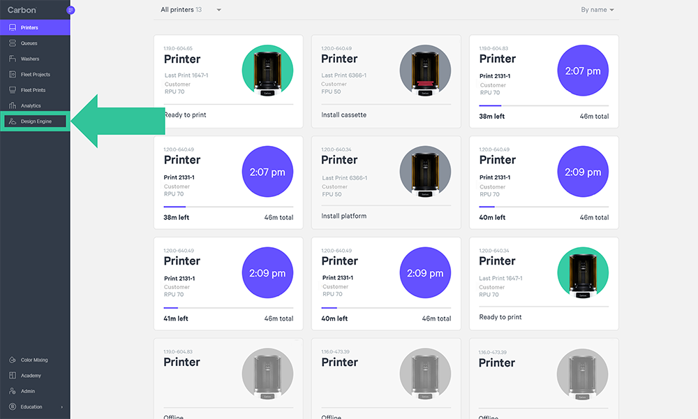
- Carbon Printer Dashboard | print.carbon3d.com Carbon printer users can access Design Engine on the printer dashboard.
Need a Design Engine Account? Sign up here for a 1 month free trial.
Basic Workflows
Create New Design
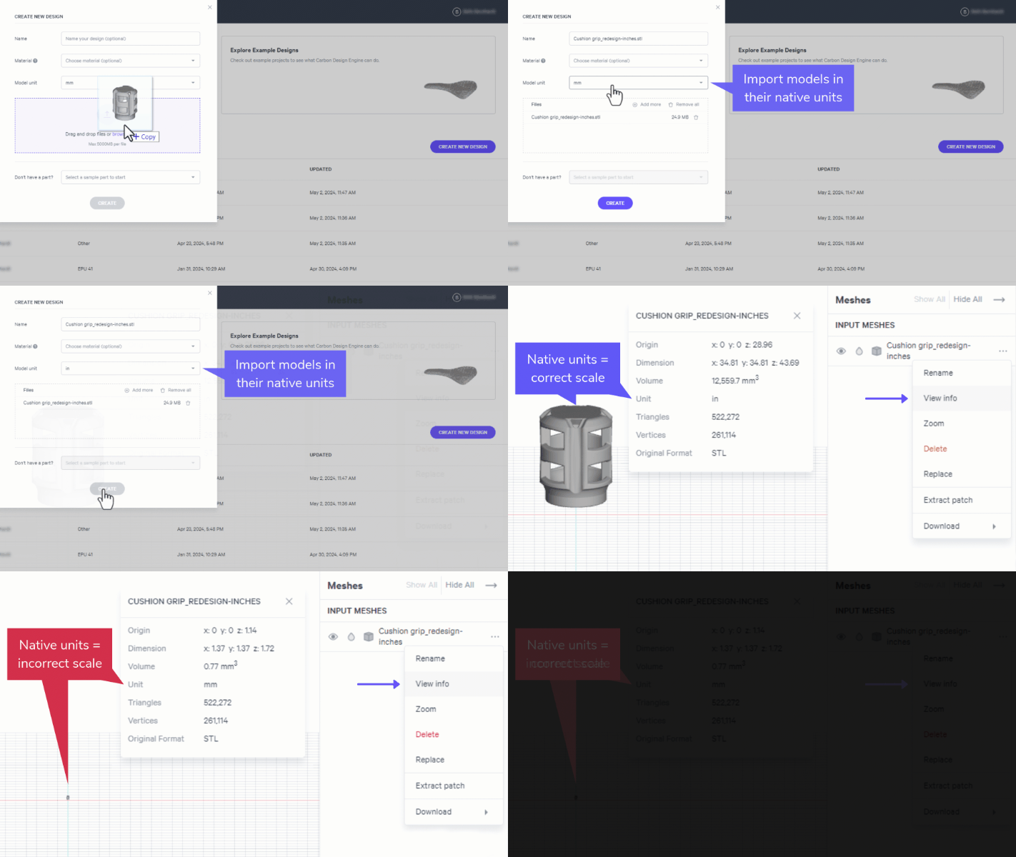
Design Engine is a software that modifies design spaces in a variety of ways for additive manufacturing. The first step is to create a design by importing your design space or optionally begin with provided shapes.
You can also use the Add Shape tool to create simple design spaces (cube, cylinder, or sphere) directly within Design Engine.
Design Workflows
Design Engine offers many design functions. Below are the most common workflows to get you started, each generating a downloadable mesh for your application.
Tet Strut Lattice with underlying tet mesh
Hex Strut Lattice with underlying hex mesh
Combine multiple STLs into one part
Texture - Noise random noise pattern on surface
Texture - Tile tiling pattern on surface
Images shown above are representative of their design category. More choices are available within each.
Tet Strut Lattice
Hex Strut Lattice
Combine
Texture - Noise
Texture - Tile
Download Design
The final step in Design Engine is to download the mesh file(s) to use in additive manufacturing.
Essential Lattice Information
Understanding the core behavior of Design Engine will give you the keys to make the most successful lattice design. Below are the topics that all new users should be aware of when creating a lattice.
The Mesh and Unit Cell
The mesh is the underlying 3-dimensional scaffold upon which your lattice is built. The mesh is comprised of unit cells upon which the strut lattice is applied.
Design Engine offers two mesh types:
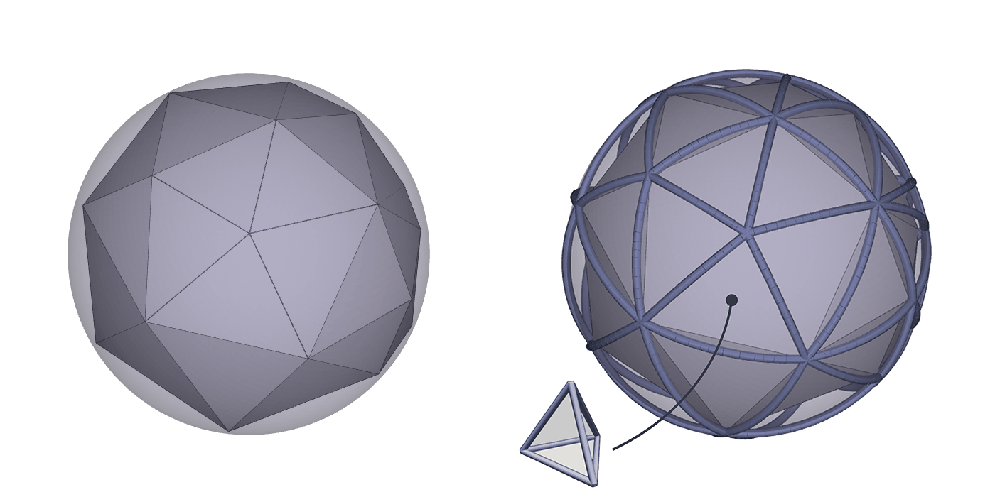
Tetrahedron Mesh (Tet) Composed of polyhedrons with 4 faces One unit cell = one tetrahedron
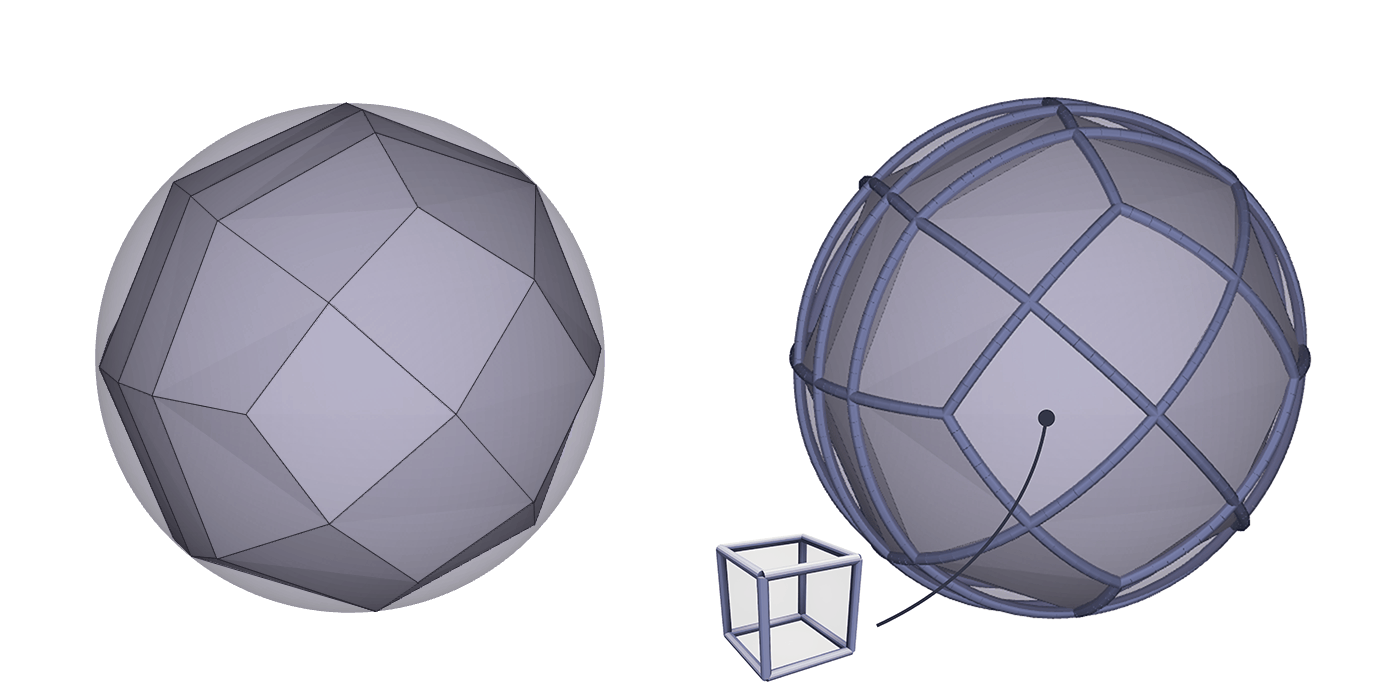
Hexahedron Mesh (Hex) Composed of polyhedrons with 6 faces One unit cell = one hexahedron
Lattice Parameters
There are four parameters that further define the lattice.
First is the material, which could be any printable material in additive manufacturing. Design Engine lattices are not limited to only Carbon resins.
The strut lattice fills in the unit cell with the remaining three parameters:
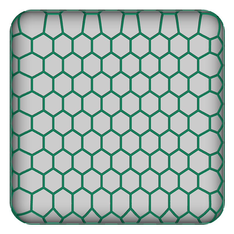
- Lattice type
- Cell size
- Strut diameter
Material
Lattice Type
Cell Size
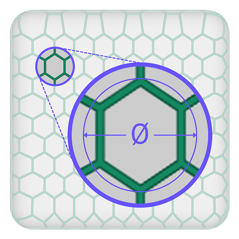
Strut Diameter
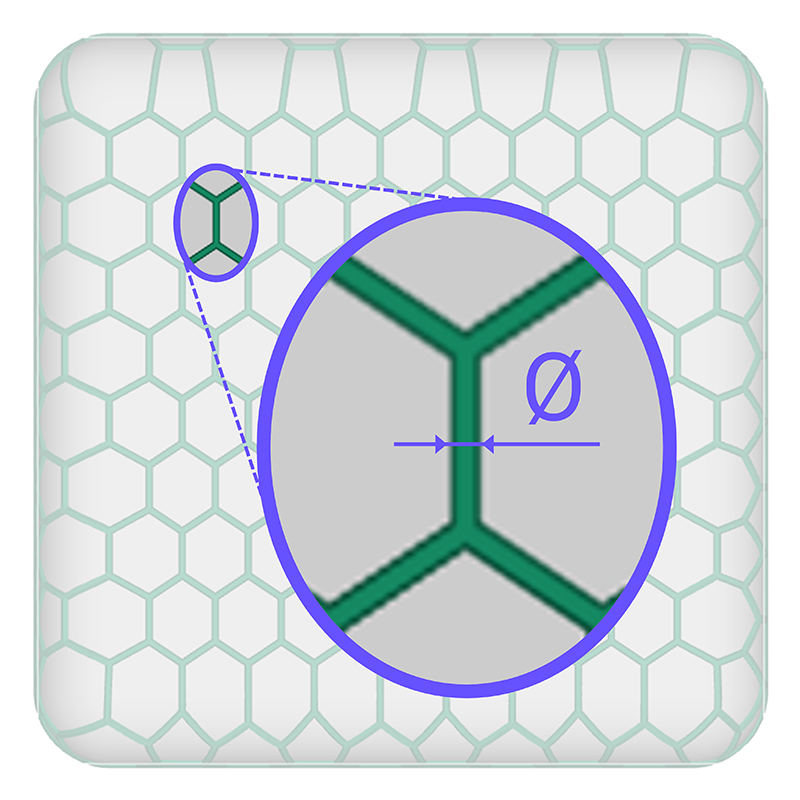
Performance and Feel
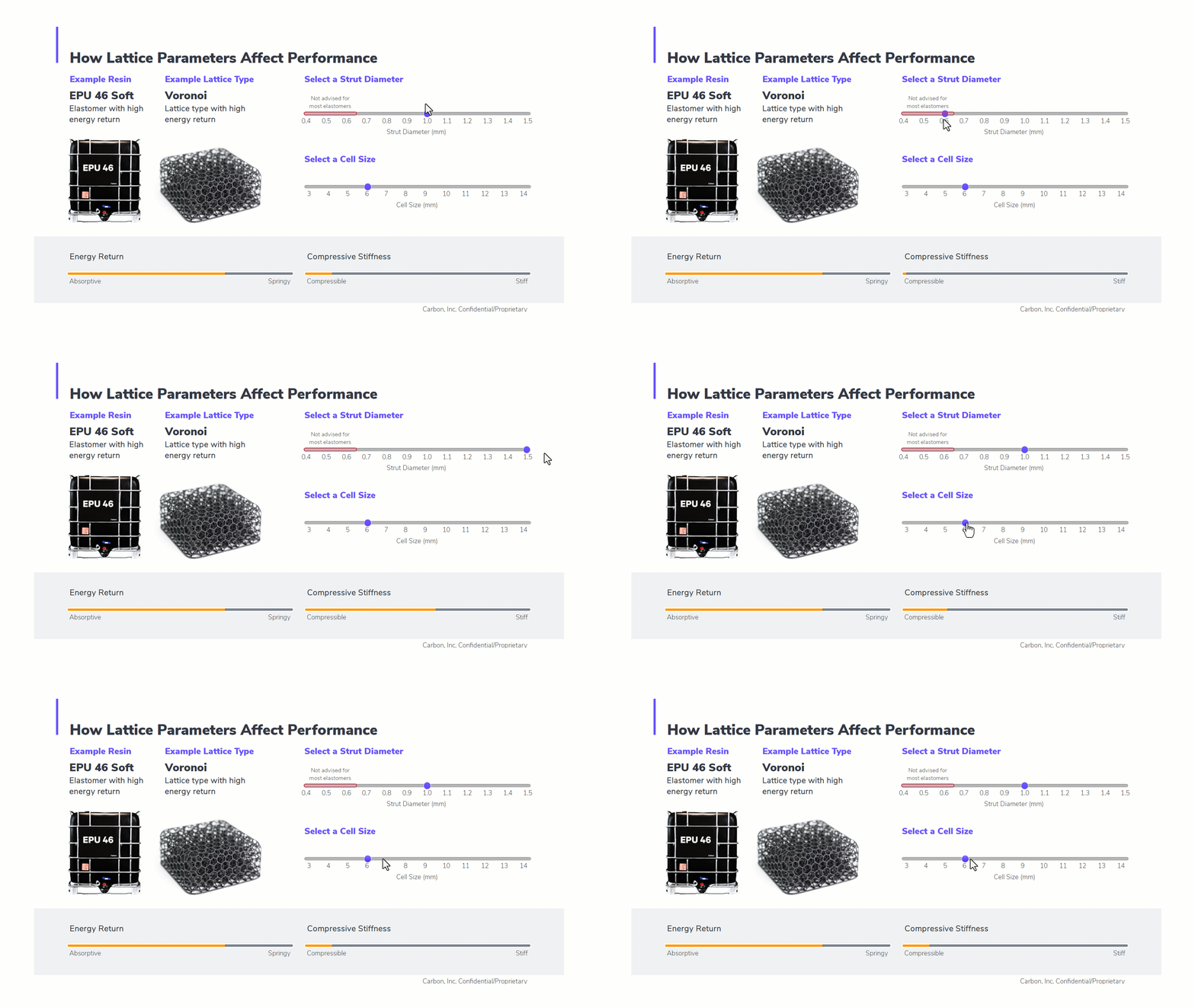
Choosing your mesh and lattice parameters provides a vast array of options for the performance of your lattice, but the relationships between these variables is simple.
Energy Return or Impact
Two variables influence the energy return or impact of a lattice, which determines how absorptive or springy the lattice performs.
- Material- resin selection
- Lattice Type - pattern selection
Compressive Strain
Two dimensional variables affect the compressive strain of a lattice, which affects how compressible or stiff the lattice performs. Some materials and lattice types are also stiffer than others.
- Strut Diameter - direct relationship
- Cell Size - inverse relationship


Strut Lattice and Solidify
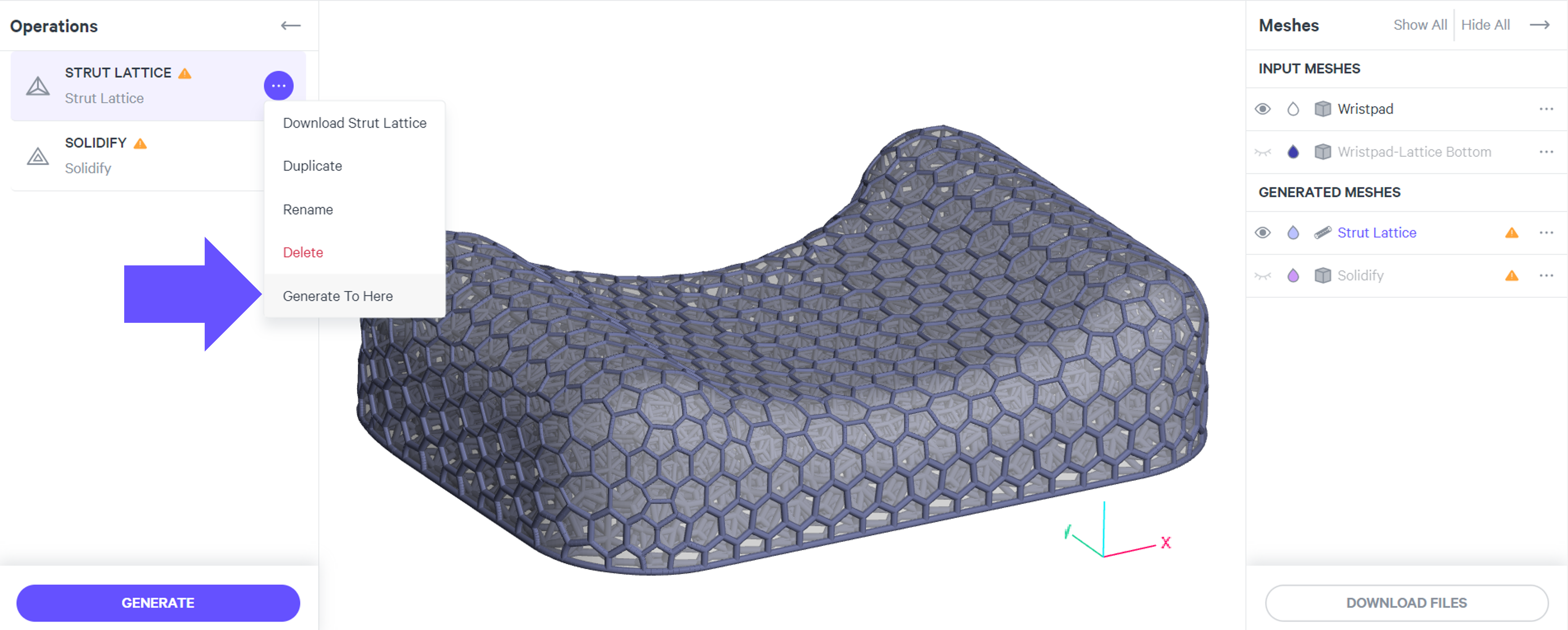
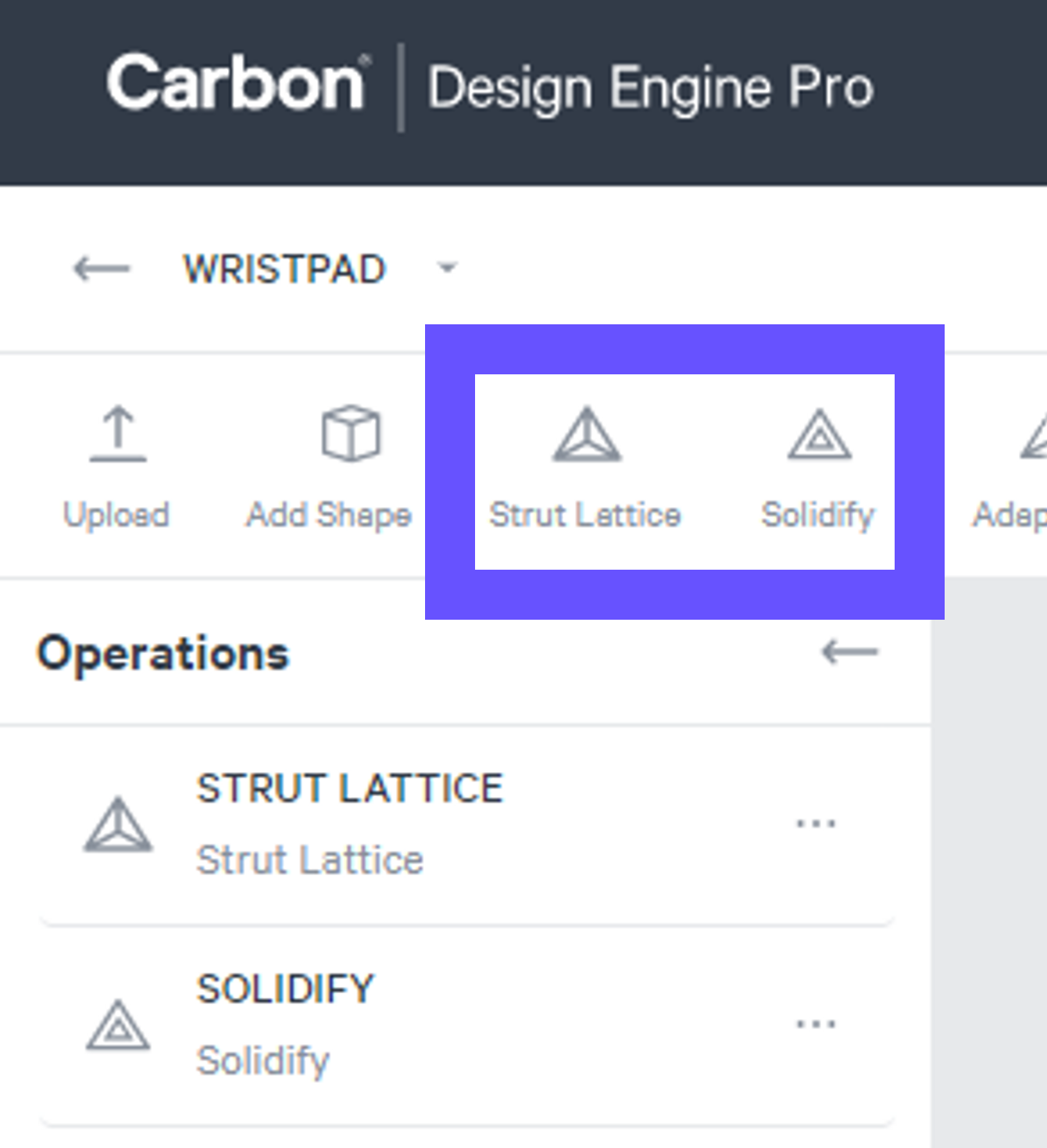
Strut Lattice and Solidify are a Team Both tools must be used to create a printable strut lattice.
Strut Lattice Strut Lattice is the foundational structure, derived from your specified parameters. At its core, this is a structure of unprintable lines and nodes.
Solidify Solidified lattices are derived from Strut Lattices but have been converted into a triangulated mesh, or STL file, for printing.
Strut Lattice and Solidify Visibility
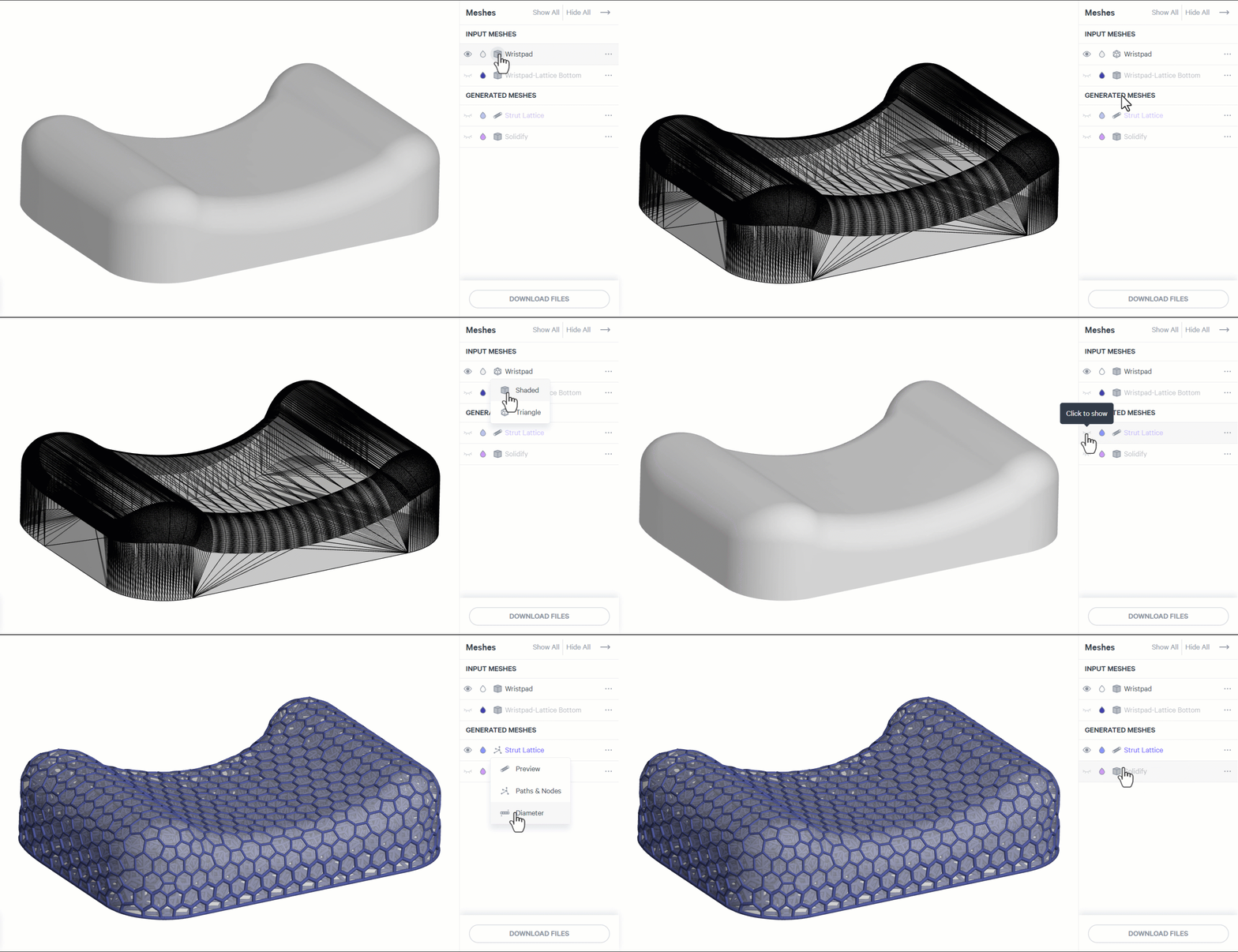
- Strut Lattice can be viewed volumetrically (Preview or Diameter) or as lines (Paths & Nodes).
- Solidify accurately depicts the printable STL file, with all utilized features in play. If you are not seeing a feature depicted in a volumetric strut lattice view, you may need to view the solidified lattice.
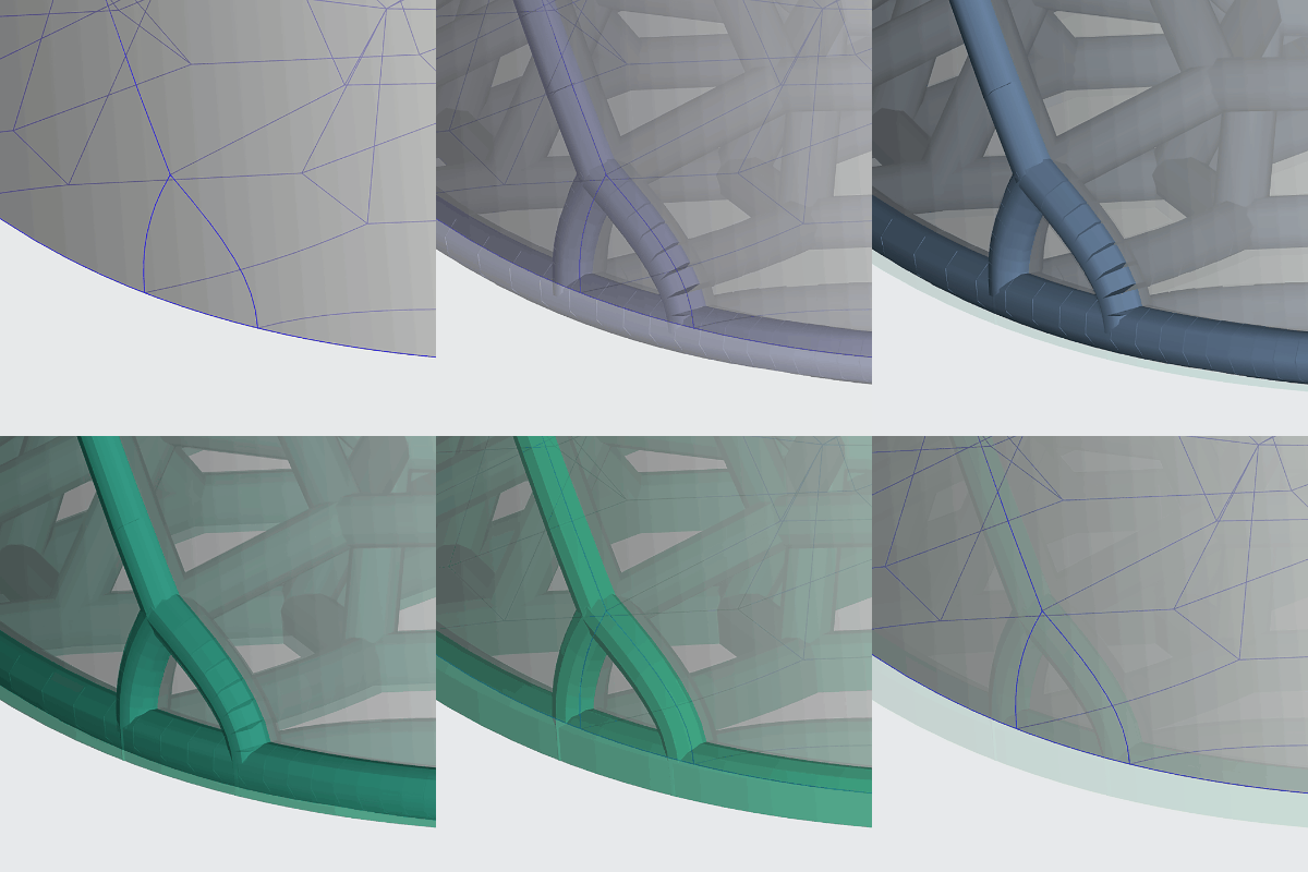
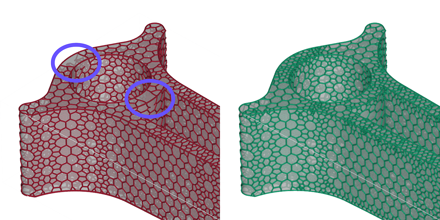
Strut Lattice The strut lattice lines are polylines, not splines, made up of line segments. The default view for Strut Lattices is to display them volumetrically with the specified strut diameter, helping you visualize the lattice in 3D. This view expands each line segment with a circular cross section of the specified diameter. Line segments along a curved strut may appear not fully connected on the outside of the curve. However, this is only a temporary visual representation and does not affect the integrity of your struts.
Solidify In the mesh conversion, all seemingly disconnected line segments are fully connected in the printable lattice.
Design Space Boundary Interface
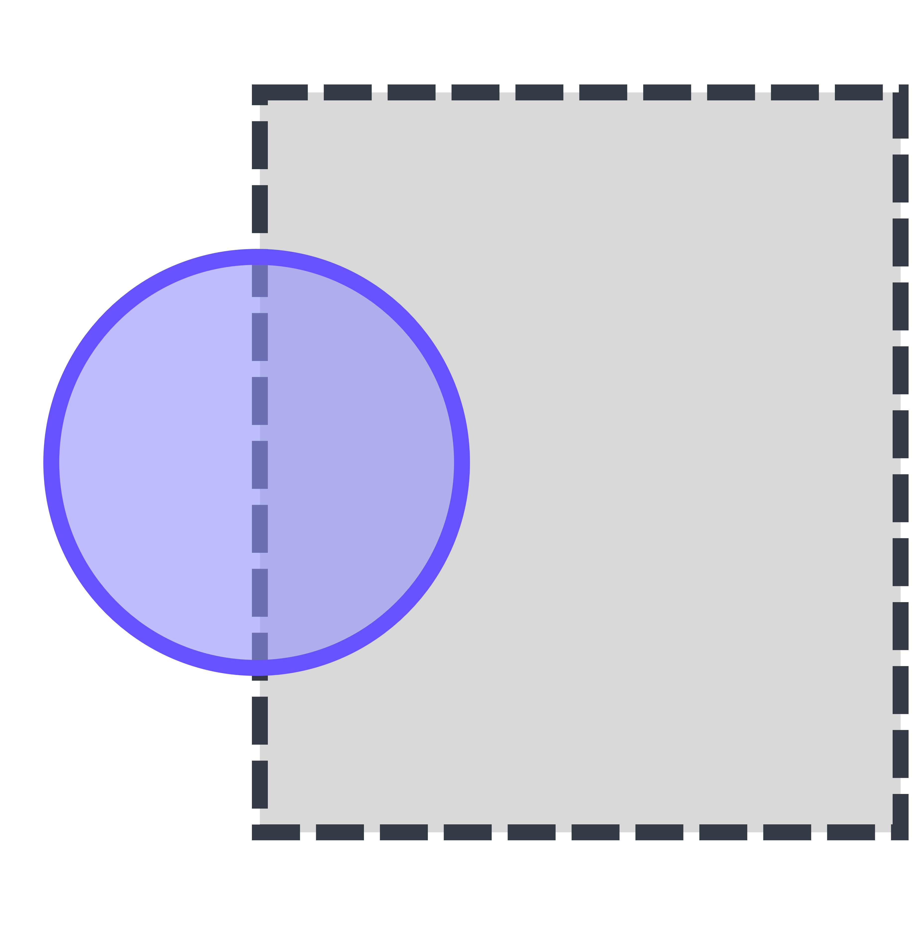
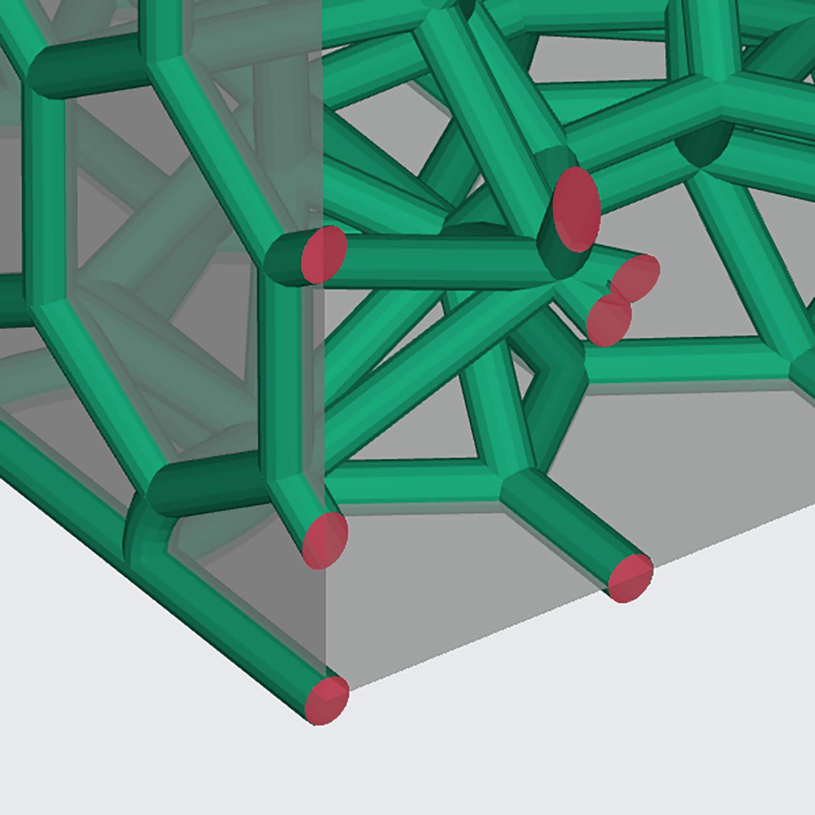
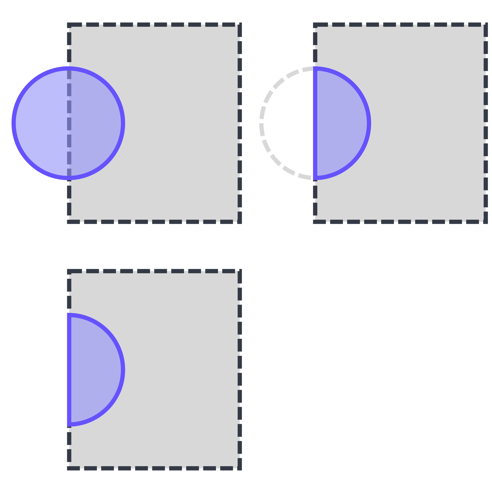
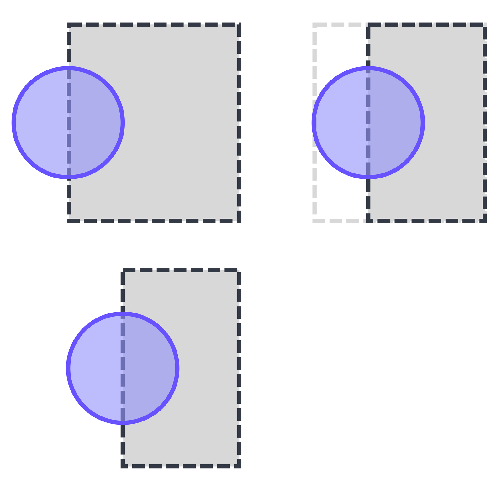
The default strut lattice generation builds outwards from the boundary mesh (your design space) by 1/2 the strut diameter.
Essential Resources
Help Topic | Reference | |
|---|---|---|
Setting up CAD Design Files | 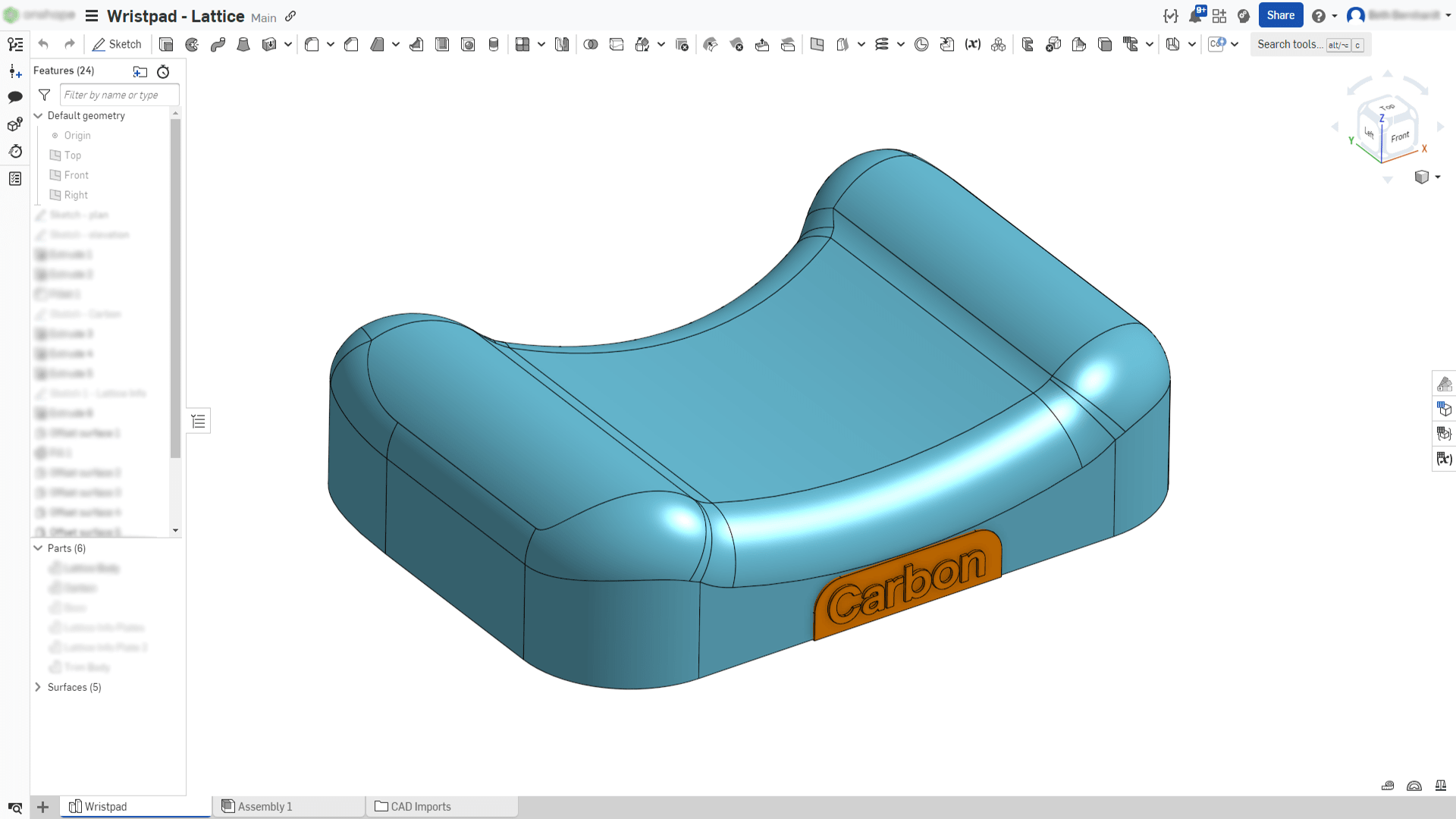 | |
Navigating Design Engine | 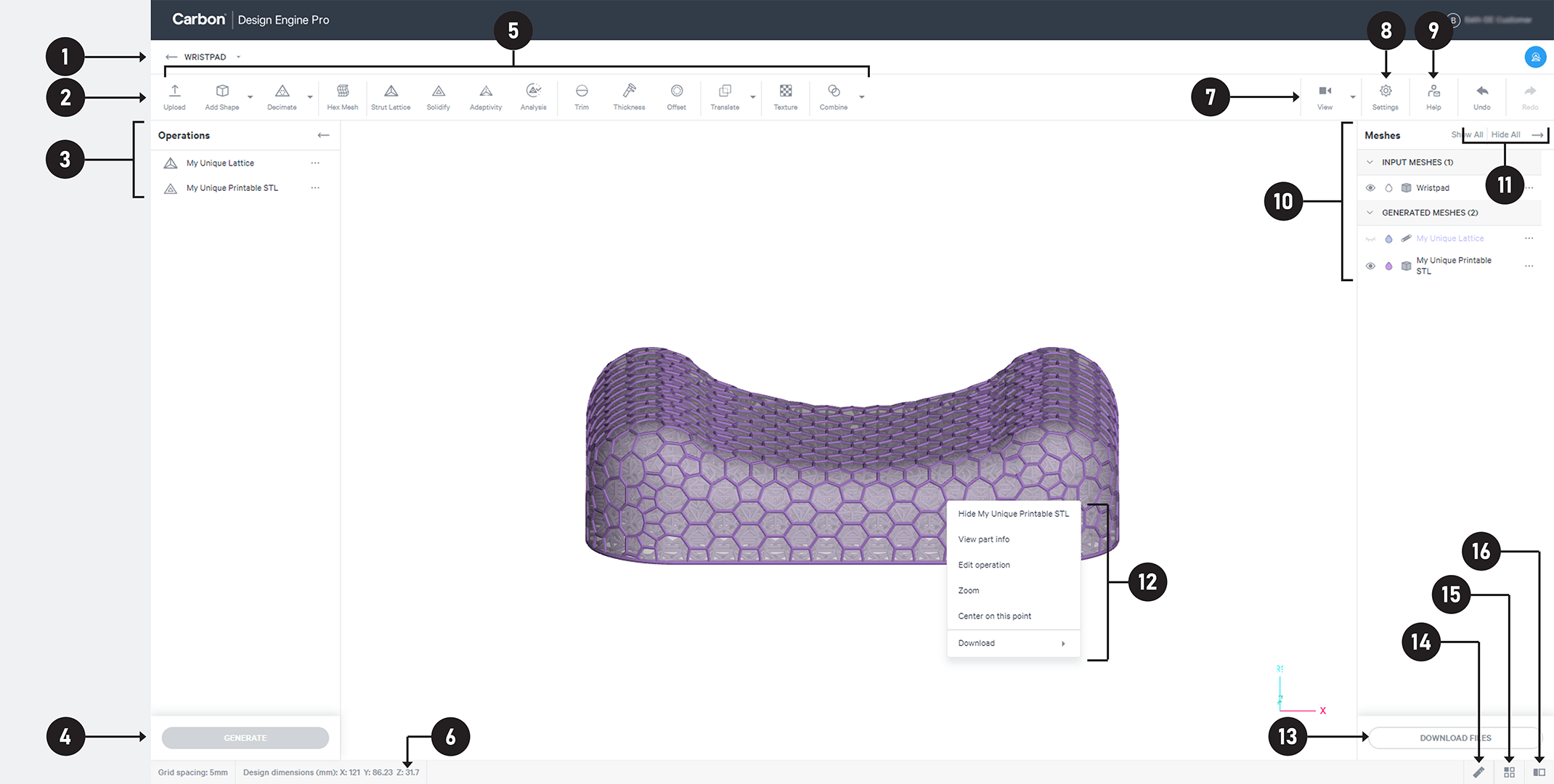 | |
Choosing Mesh Type | 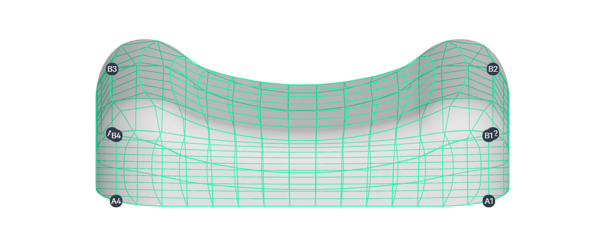 | |
Selecting a Material | 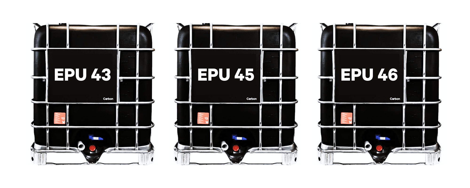 | |
Selecting Unit Cell Manually | 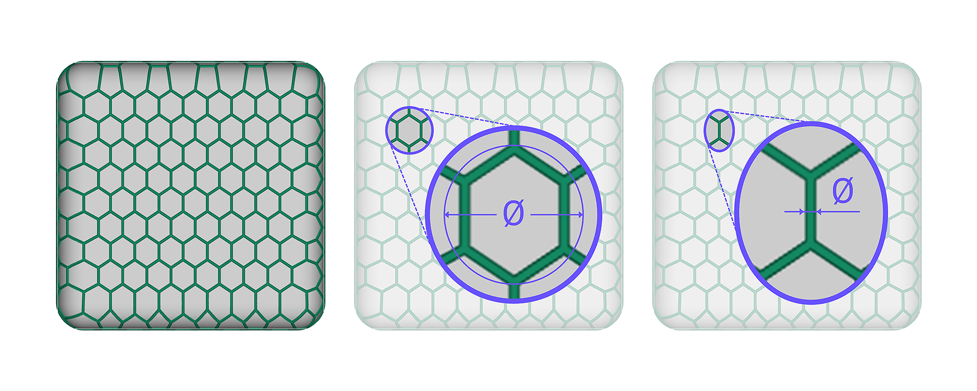 | |
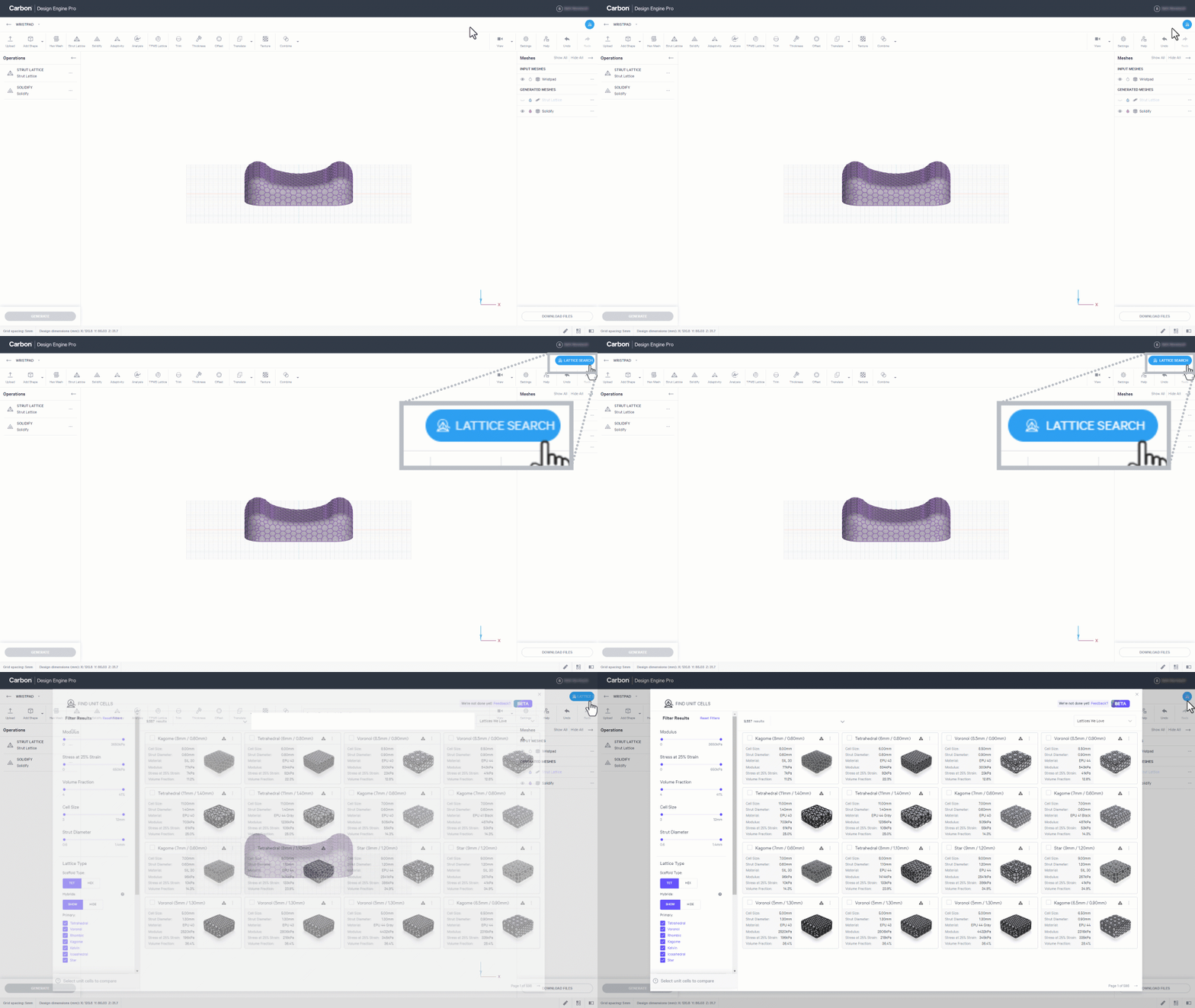
Selecting Unit Cell via Lattice Search | 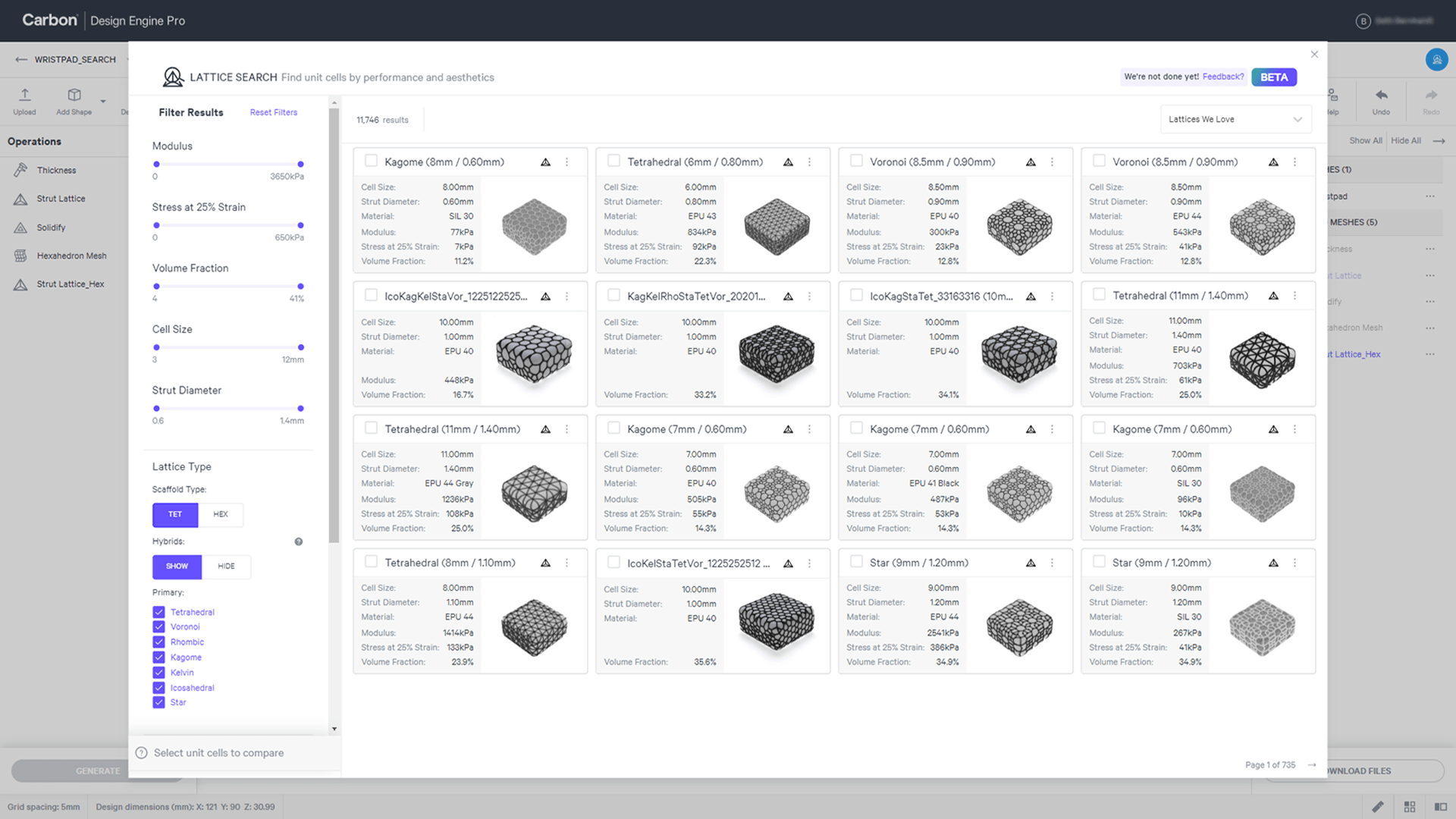 | |
Understanding What Design Engine Can Do | 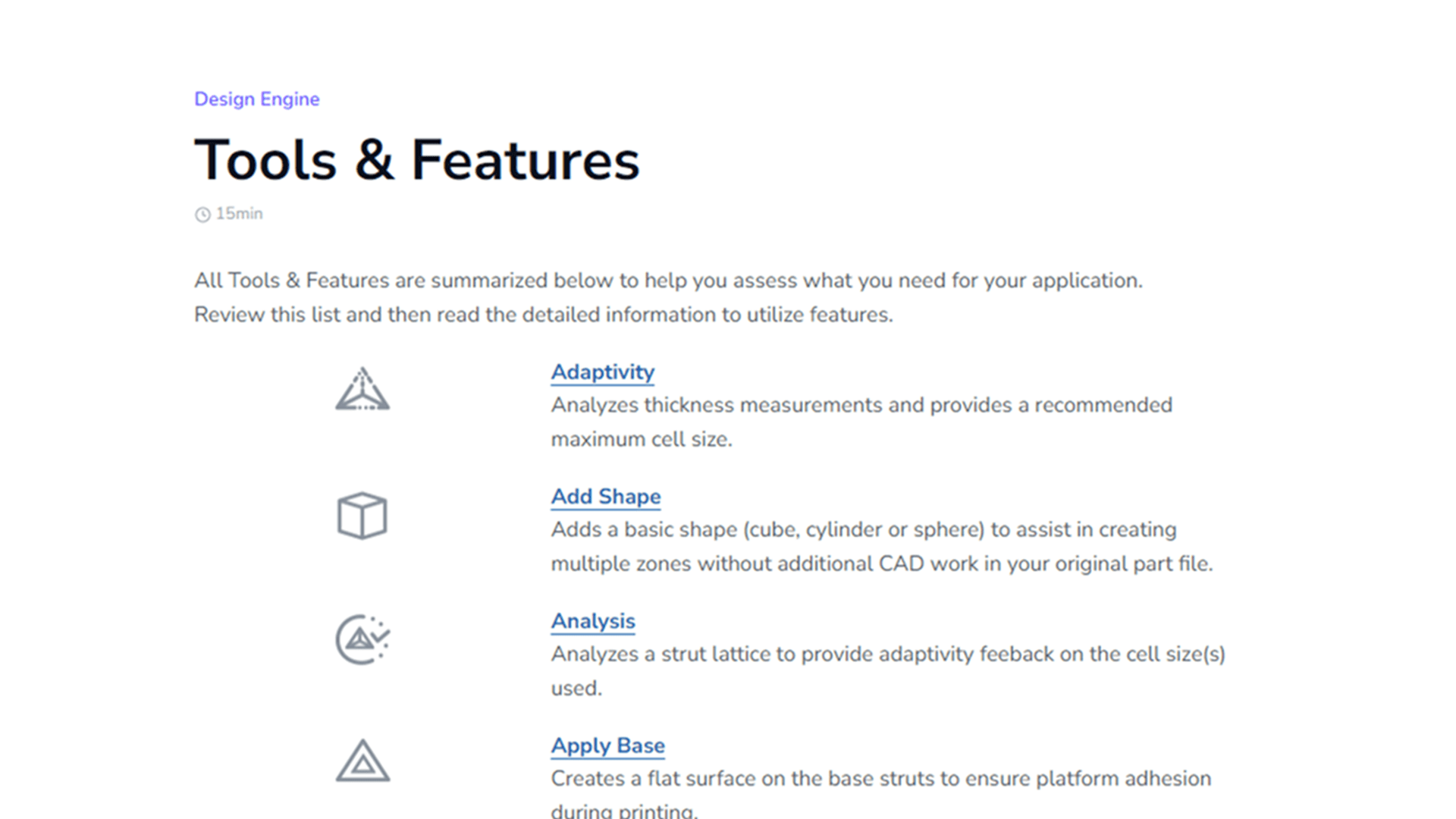 | |
Assessing Manufacturability | 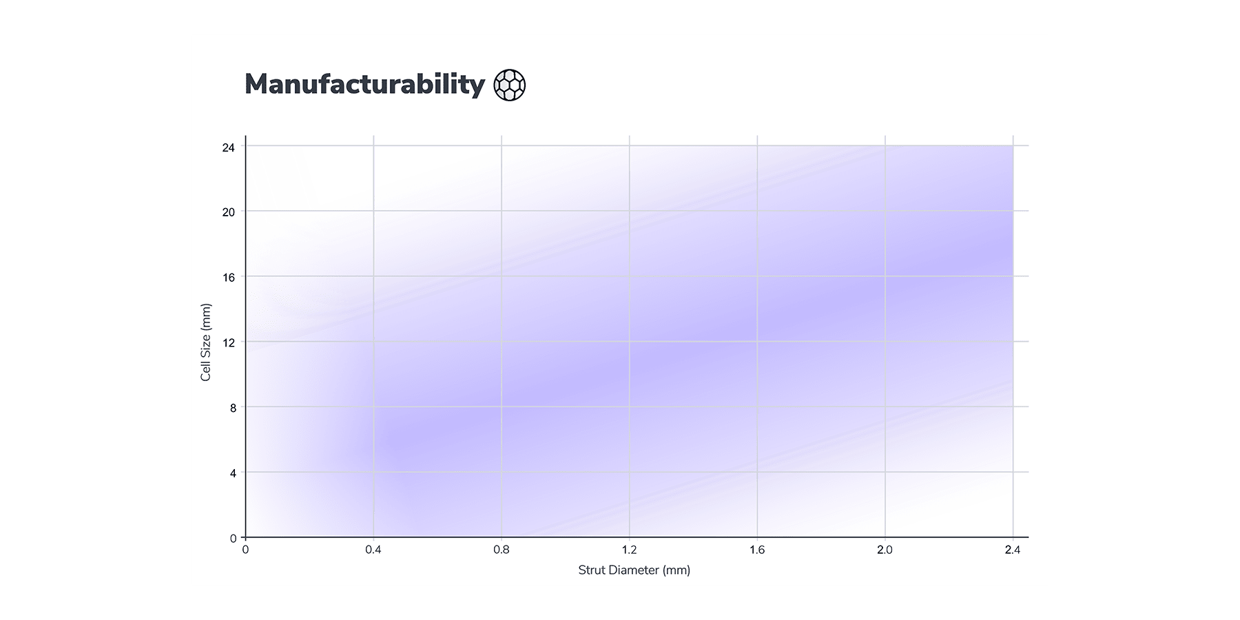 |