---
title: Supports
slug: software/supports
description: Unlock the full potential of your 3D printing projects with this guide on creating supports in Carbon's printer software. This document explores the vital role of supports in print success.
docTags:
createdAt: 2024-07-01T22:43:42.753Z
---
## Conditions that Require Supports
Supports are a temporary structure, printed in the same material as the part, that may be required to ensure successful printing. Supports are removed after printing. Conditions that require supports are:
::::VerticalSplit{layout="right"}
:::VerticalSplitItem
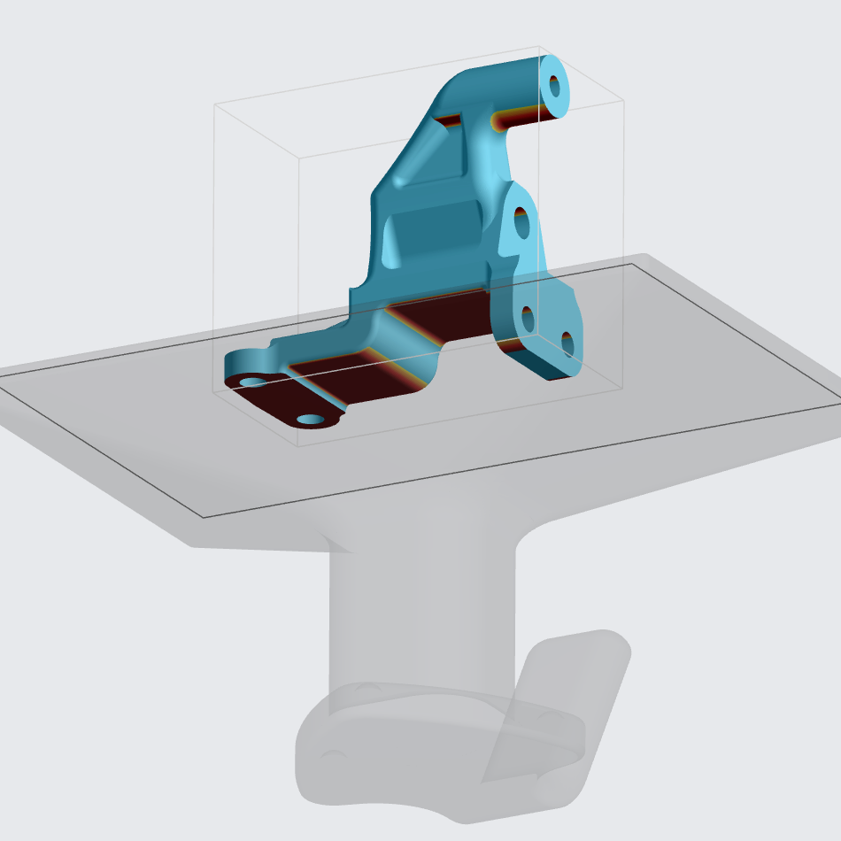
**Overhangs** (and Bridges)
Any feature that projects from the part either horizontally (parallel to the platform) or below the recommended self-supporting angle. (Shown in red)
Reference [recommended features sizes](docId\:t94PR-A-C0pIhY6LJsWk7) for overhang distance and self-supporting angles per resin.
:::
:::VerticalSplitItem
:::
::::
::::VerticalSplit{layout="right"}
:::VerticalSplitItem
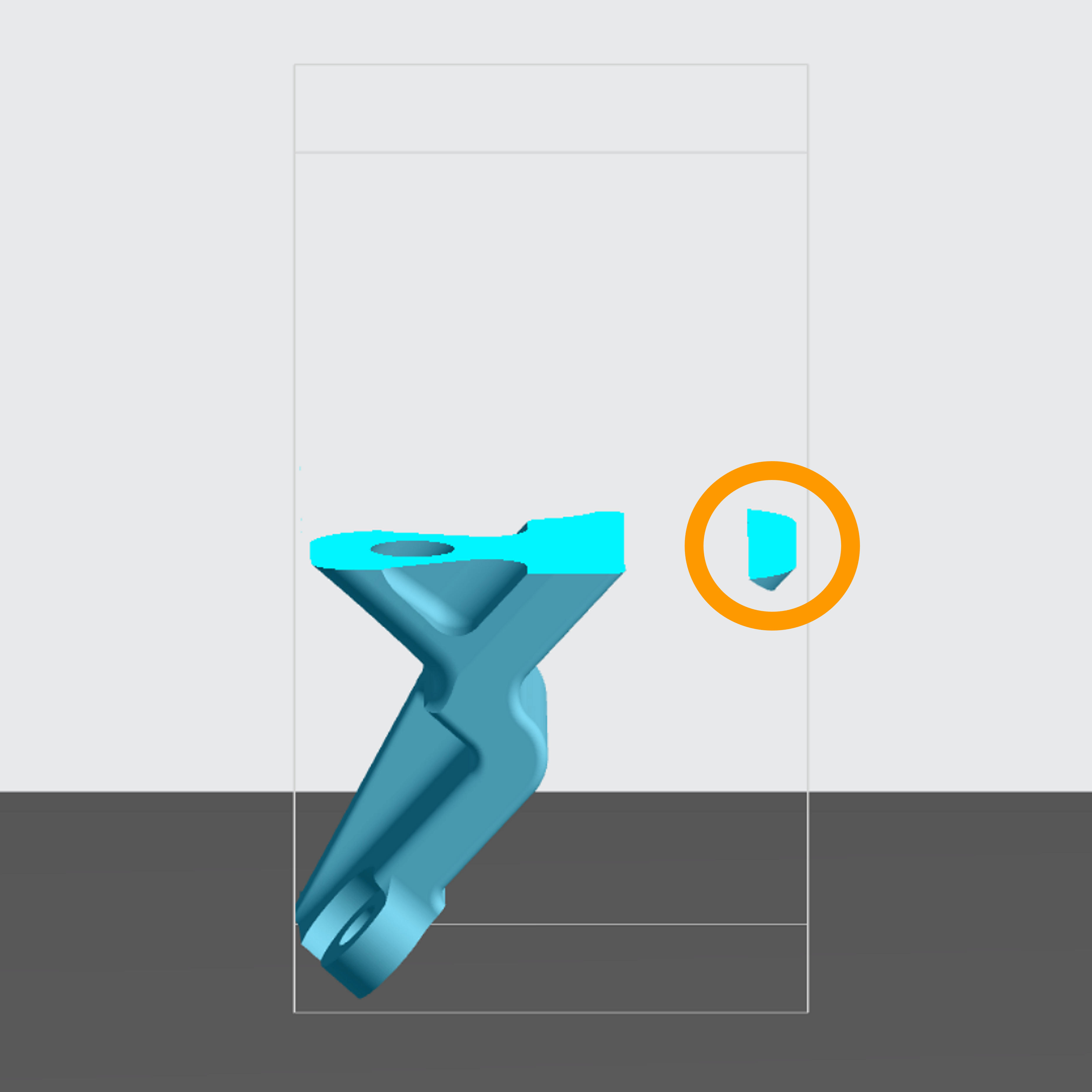
**Island**
A feature that begins printing above the platform before it is connected to the rest of the part.
:::
:::VerticalSplitItem
:::
::::
::::VerticalSplit{layout="right"}
:::VerticalSplitItem
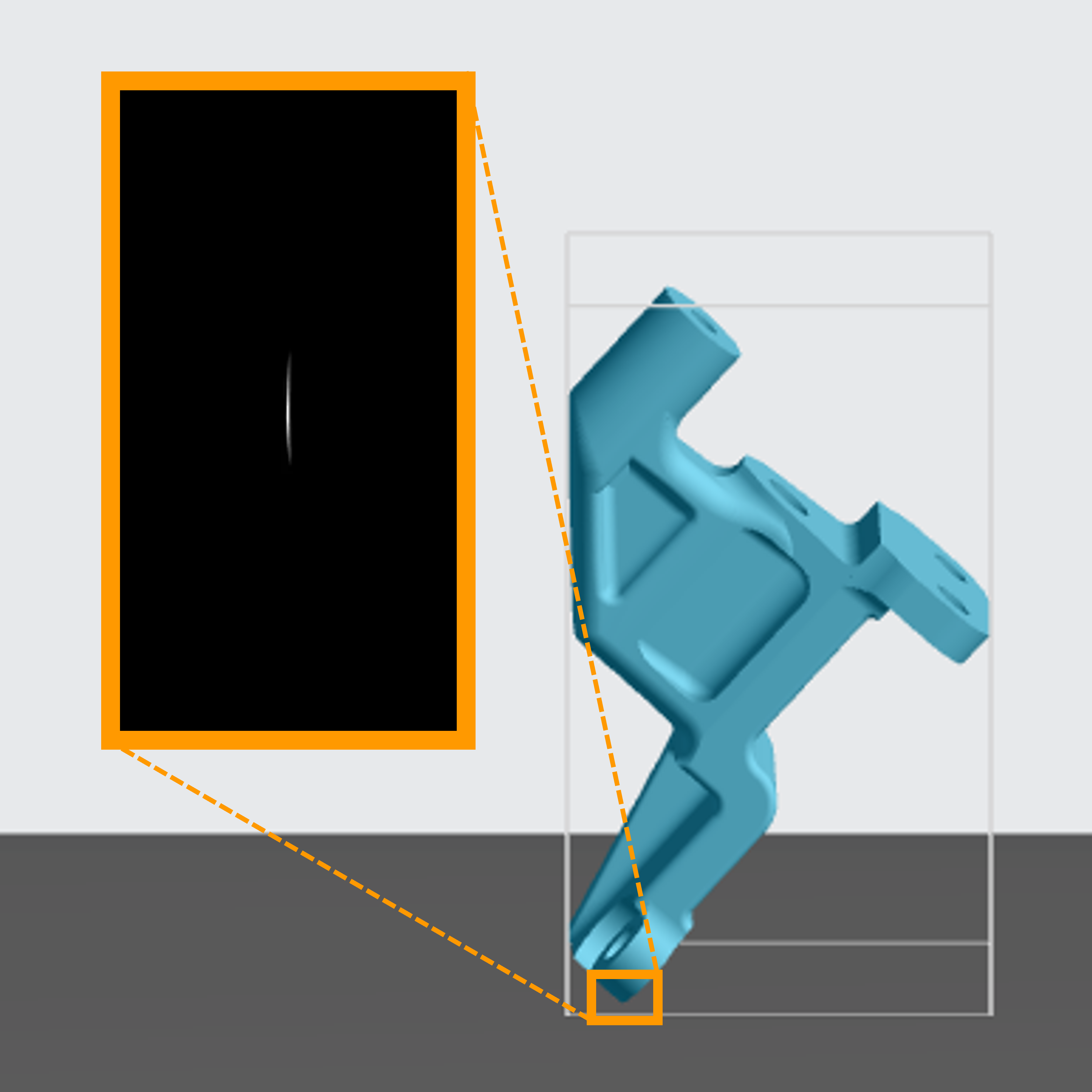
**Adhesion**
When a part or its orientation does not have enough surface contact with the platform to hold on at the start of a print, adhesion supports or a different orientation are needed.
Reference [DLS Printer Dynamics](docId\:U7XYytjyDp3BvsYy2qKcU).
:::
:::VerticalSplitItem
:::
::::
::::VerticalSplit{layout="right"}
:::VerticalSplitItem
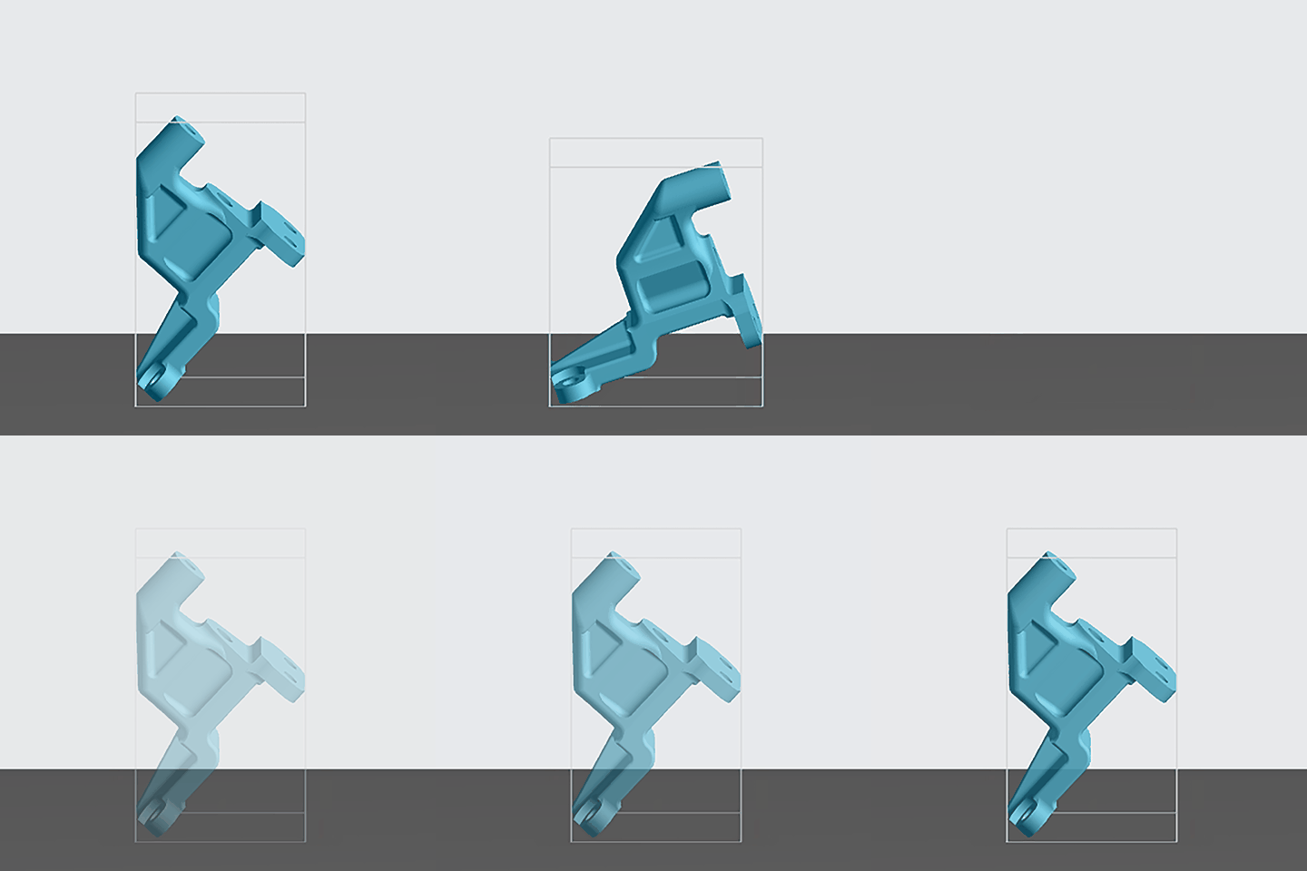
**Stability**
Supports are needed to allow the part to withstand the suction forces of printing.
Reference [DLS Printer Dynamics](docId\:U7XYytjyDp3BvsYy2qKcU).
:::
:::VerticalSplitItem
:::
::::
Apply supports **after orienting** your part.
This guide will show you what **tools** you have available inside the Printer UI and **how to use them**.
Part supports **strategy** is a topic covered in detail in the [Orientation & Supports](https://docs.carbon3d.com/training/orientation-supports-factors/index.html) guide.
:::hint{type="info"}
Parts **designed** for DLS™ production can greatly reduce or eliminate the need for supports.
:::
## Supports are Resin Specific
::::VerticalSplit{layout="middle"}
:::VerticalSplitItem

:::
:::VerticalSplitItem
Carbon's supports are calibrated to suit the selected resin.
- **Support parameters **are based on the resin to provide an optimal balance of stability and ease of removability.
- For Auto Supports, **density and quantity **of supports varies per resin.
You must **select your resin first before creating a support structure****.** If you do change the resin after creation of supports, the software will give you a warning to verify if you want to keep the previous support structure or clear supports.
:::
::::
## Regenerate Supports
After transforming a supported part, you have the option to regenerate supports. Selecting **yes will regenerate supports **based on the existing support points, while selecting **no will delete supports**.
*Available in software v1.43 and higher.*
Transforms include:
- Orienting
- Toggling between on/above platform
- Spinning/rotating
- Scaling
::::VerticalSplit{layout="middle"}
:::VerticalSplitItem
**Supports Regenerate After Transform**
:::
:::VerticalSplitItem
**Enable Feature for Projects Created Prior to v1.43**
:::
::::
::::VerticalSplit{layout="middle"}
:::VerticalSplitItem

- Transform part
- Hover over Regenerate Supports dialog to view support points
- Select Yes for supports
- Transform may negate some supports
:::
:::VerticalSplitItem

**Without action** - Project created before v1.43
- Transform part
- **⚠︎ ****SUPPORTS GONE**
**To enable feature**
- Delete or add any support
- Undo action if desired
- Project ready for v1.43 functionality
:::
::::
:::hint{type="danger"}
Note that if you want to regenerate supports, you must **select Yes in the prompt immediately **before taking any other actions (such as adding additional supports or refreshing the page). Otherwise the functionality will be lost and supports will be cleared.
:::
:::hint{type="info"}
Supports may revert back to default parameters when regenerated after a transform. Double check support parameters and rebuild as needed where different support parameters are desired.
:::
## Part Position
While orienting and supporting your part, you will need to decide if the part should be **Above Platform **or **On Platform**. The primary considerations are as follows. Assess each consideration for each potential orientation.
::::VerticalSplit{layout="middle"}
:::VerticalSplitItem
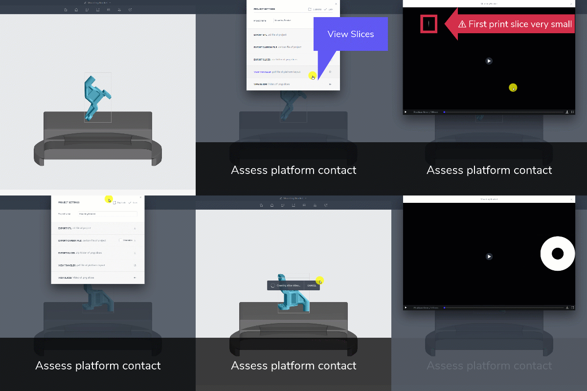
**Platform Contact**
- Open Project Settings
- View Slices
**⚠ ****First print slice very small**** - Above Platform**
**First print slice good contact**** - On Platform**
:::
:::VerticalSplitItem
:::
::::
***
::::VerticalSplit{layout="middle"}
:::VerticalSplitItem
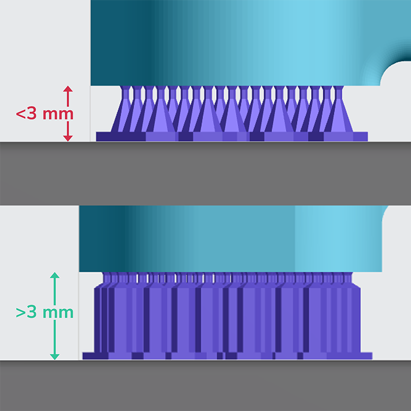
**Feature Distance from Platform**
- **Less than 3 mm** **- Above Platform**
- **Greater than 3 mm**** - On Platform**
Supports \<3mm tall are less effective and more difficult to remove.
:::
:::VerticalSplitItem
:::
::::
***
::::VerticalSplit{layout="middle"}
:::VerticalSplitItem
**Unvented Volumes**
- Print defect from unvented volume
- Unvented volume with on platform auto orientation
- No unvented volume lifted above platform
**Above Platform**
Lifting a part onto supports will eliminate unvented volumes when the unvented cavity sits on the platform.
:::
:::VerticalSplitItem

:::
::::
:::hint{type="info"}
Your part will be lifted **Above Platform** if you select that option and run **Auto Orientation** in the Orient tab.
:::
:::hint{type="warning"}
If you did not Auto Orient your part, then you will need to actively select **Above Platform** in the **Supports** tab (the part will not default to Above Platform).
:::
:::hint{type="info"}
Note that the **Above Platform **choice lifts your part **6 mm** above the platform.
Above Platform orientations always **require supports**, but more options are available.
:::
:::hint{type="info"}
If you prefer to change the default part position to **On Platform**, you may do so in your project settings. The setting is named **Default part position for auto orientation **(printer requires 1.36 software version).
:::
# Types of Supports
::::VerticalSplit{layout="middle"}
:::VerticalSplitItem

:::
:::VerticalSplitItem
There are two types of supports offered in the software, each providing unique benefits:
- **Fence Supports**
- **Bar Supports**
Supports are printed in the same material as the part and are removed from the part after printing, leaving behind small **support nubs **on the surface of the part that you see here.
:::
::::
## Fence Supports
Fences are narrow, perforated walls that are extruded **from polylines **defined on the part.
Fence supports can be **added manually **to your support structure.
**How Fence Supports Work**
- Created by defining polylines on your part surface
- Connect at the part with a series of tapered points that are narrowest at the part surface, where the support breaks off during removal
- Tall fence supports lose stiffness and can move or buckle unless strengthened (see 💡 Tips & Tricks below)
::::VerticalSplit{layout="middle"}
:::VerticalSplitItem

:::
:::VerticalSplitItem

:::
::::
::::VerticalSplit{layout="middle"}
:::VerticalSplitItem
**When to Use Fence Supports**
- Along edges
- When surface finish is important
- When less than \~30 mm tall
:::
:::VerticalSplitItem
**When ****NOT**** to Use Fence Supports**
- When greater than \~30 mm tall (unless strengthened per 💡Tips & Tricks)
:::
::::
**💡 Tips & Tricks for Taller Fence Supports**
The downside to fence supports is that they are not always strong enough to be relied on for stability, with the default settings not performing well when fences are tall (over \~30 mm).
There are a couple tricks to make fence supports stronger and more effective at taller heights.
::::VerticalSplit{layout="right"}
:::VerticalSplitItem
**Adjust Parameters **- Increase the wall thickness
Learn more about editable support parameters [here](docId\:VUbpoAitbLM11aM9-qJ1p).
:::
:::VerticalSplitItem

:::
::::
::::VerticalSplit{layout="right"}
:::VerticalSplitItem
**Hybrid **- Use fence supports on edges and bar supports in the center for stability
:::
:::VerticalSplitItem

:::
::::
::::VerticalSplit{layout="right"}
:::VerticalSplitItem
**Matrix **- Build fence supports in a grid pattern to make them structurally stronger
:::
:::VerticalSplitItem

:::
::::
## Bar Supports
Bar supports are hexagonal rod structures that attach at a **single point **on the surface. A collection of bar supports automatically truss together\* to create a strong, stable support structure. **Auto supports **utilize bar supports, and you can also **manually add **bar supports.
*\*Supports generated at the same time will truss together. Points generated in a separate operation will not truss with existing supports, only with supports in the same operation.*
**How Bar Supports Work**
- Created by defining points on your part surface
- Connect at the part with a wide tip and taper to a neck that serves as the break point
- Beyond the break point, the bar widens to its main diameter, until it reaches the platform for an even larger base structure for adhesion.
::::VerticalSplit{layout="middle"}
:::VerticalSplitItem

**When to Use Bar Supports**
- For stability
:::
:::VerticalSplitItem

**When ****NOT**** to Use Bar Supports**
- When surface finish is important, due to larger support nubs on surface
:::
::::
# Manual Supports
::::VerticalSplit{layout="middle"}
:::VerticalSplitItem

:::
:::VerticalSplitItem
Manual supports is the best option for creating an **efficient production build**.
A selection of tools are available to provide both types of supports (fence and bar), as well as the ability to fine tune the support parameters for your build conditions.
Choosing where and how supports are added to your parts allows you to make the best decisions for your application regarding [design, cost and print success](docId\:DoBa4qKKoXpi-52yw3nCr).
:::
::::
There are three methods for manual supports and some general guidelines that apply to all:
::::VerticalSplit{layout="middle"}
:::VerticalSplitItem
- [Patch](docId\:VUbpoAitbLM11aM9-qJ1p)
- [Fence](docId\:VUbpoAitbLM11aM9-qJ1p)
- [Bar](docId\:VUbpoAitbLM11aM9-qJ1p)
:::
:::VerticalSplitItem
- [Editing Supports](docId\:VUbpoAitbLM11aM9-qJ1p)
- [Deleting Supports](docId\:VUbpoAitbLM11aM9-qJ1p)
- [Editable Support Parameters](docId\:VUbpoAitbLM11aM9-qJ1p)
:::
::::
:::hint{type="info"}
**Multiple areas and types of supports can be generated at once.**
For example, you can have multiple patch sections, each with different parameters. Multiple fence polylines can also be drawn with separate parameters, and all can be generated at once, with the patches, even on multiple parts.
:::
## Patch
Patch is the **quickest method **to apply supports to a surface. Both** fence and bar support types **can be generated with the patch tool.
Select **Patch** menu under **Manual** tab

:::ExpandableHeading
Video Text
- Select a surface where supports are needed
- Adjust overhang angle to highlight the surface you need
- Select support type: Bar, Fence, Boundary Fence Only
- Adjust spacing to increase/decrease density of supports
- Optionally edit primary support parameters
- Optionally include a boundary of fence\* supports on edges
- Adjust Margin to specify distance from edge
- Optionally edit boundary fence parameters
- Click Generate All
:::
:::hint{type="warning"}
\*Including the boundary fence is generally advised unless the fence causes cleanability issues.
:::
### Base Raft Option
The Base Raft option automatically places supports closer together with large bases that connect many (or all) supports together as a “raft.”
This option was created for certain dental applications to create supports compatible with automatic part removal via the AO Backpack, part of Carbon’s Automatic Operation suite of products.
:::hint{type="warning"}
**All patch supports that will be printed in Automatic Mode require the use of base rafts**.
:::
:::hint{type="info"}
While this feature has primarily been tested with certain types of supported dental models printed in **DPR10**, all users are able to access this feature when using patch supports.
Note that selecting “Base Raft" pre-sets the Bar Spacing and Base Diameter parameters and disables the Boundary Fence for these dental applications; however, all parameters remain editable to provide flexibility for a wide range of use cases.
:::
::::VerticalSplit{layout="middle"}
:::VerticalSplitItem
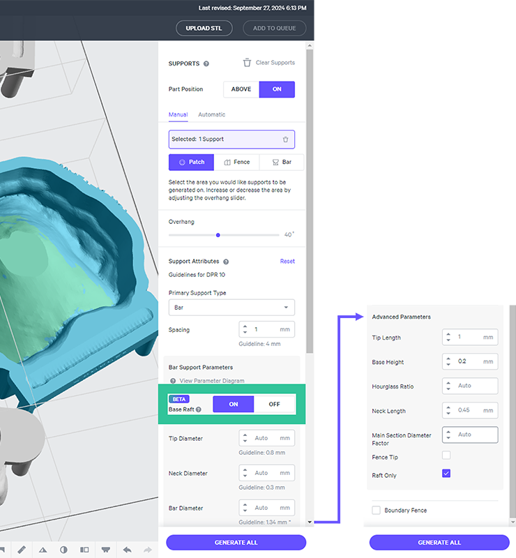
**Generate Base Raft for Patch Supports**
- Go to the Supports tab
- Select a **patch** for the area to be supported, following overhang guidelines for the model type.
- Under **Bar Support Parameters, **toggle **Base Raft to ON.**
- Use default parameter settings or adjust as desired.
*Default settings are optimized for use with the AO Backpack and DPR 10 dental models/dies.*
- Click **Generate All. **
*Dismiss any notifications of supports that could not be generated.*
:::
:::VerticalSplitItem
:::
::::
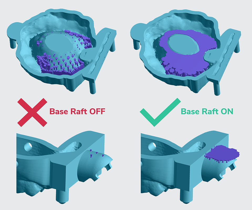
**Example Base Rafts in Dental Applications**
::::VerticalSplit{layout="middle"}
:::VerticalSplitItem
The left shows examples of **bad** supports for Auto Mode generated with **Base Raft OFF.** Small, disconnected bar supports and fence supports will leave debris in the cassette and cause either delays for debris removal or Auto Mode to turn off.
:::
:::VerticalSplitItem
The right shows examples of **good** supports for Auto Mode generated with **Base Raft ON**. Supports are spaced closer together with large bases that connect most, or all, supports together.
:::
::::
### Patches as Edge Constraints
Existing patches can be used as an edge constraint for new patches in software release v1.37 and above. Previous software versions used the overhang angle only as an edge constraint, overlapping existing patches if present.
Strategically, this allows you better control over where supports are placed, or what parameters are used within patches.

## Fence
Select **Fence** menu under **Manual** tab

:::ExpandableHeading
Video Text
- Click points to draw a polyline
- Click **esc **when done with a polyline
- Hold **shift **to snap to an edge
- Click on polyline to select for editing
- Click new point to extend
- Draw window over point to select and
- Click on polyline to select for editing
- Hold **E **and click & drag a point for fine tuning
- Select straight tip for horizontal surfaces
- Or angled for angled surfaces
- Clicking
:::
:::hint{type="info"}
Note that when a polyline is selected in **green**, it is **editable.**
When the polyline is **red**, it is selected **for deletion.**
:::
## Bar
Select **Bar** menu under **Manual** tab

:::ExpandableHeading
Video Text
- Click multiple points for bar supports
- Click Generate All
- Multiple bar supports generated at the same time truss together
- Hold **shift **to snap to an edge
- New points truss together but remain separate from existing supports
:::
::::VerticalSplit{layout="middle"}
:::VerticalSplitItem
**Control Connection Points**
- Click start point
- Hold **CTRL **for end point
Magenta indicates sub-optimal location
- Click end point
- Repeat as needed
- Generate All
:::
:::VerticalSplitItem

:::
::::
:::hint{type="info"}
Note that the size of the dot on the part while creating fence and bar supports is not representative of the size of the support tip that will be generated, which varies by resin.
:::
## Editing Supports
The start/end points of bar supports and the polylines of fence supports can be edited after they are generated. Only one support can be edited at a time, and processing support edits on large, complex models may be slow. Press **Esc** to cancel a support edit if desired.
*Available software v1.43 and higher*
**Bar Supports**
::::VerticalSplit{layout="middle"}
:::VerticalSplitItem

**Edit Bar Support Location**
- Click on support
- Click edit bar
- Move tip location
- Magenta indicates sub-optimal surface
- Click to set location
- Move base location
- Can place on part
- Or on platform
:::
:::VerticalSplitItem

**Edited Support Connection May Differ**
The algorithm building supports may make unexpected decisions when editing supports. Differences most likely occur:
- On steep surfaces
- When supports truss together
Click undo and try again with slight variation until satisfied with results.
:::
::::
::::VerticalSplit{layout="middle"}
:::VerticalSplitItem

:::
:::VerticalSplitItem
**Edit Fence Support Location**
- Click on support
- Click edit fence
- Move polyline control points
- Hold **E **while clicking and dragging points
- Click on part to add new points to extend polyline
- Click Generate All when editing is complete
:::
::::
*Delete points:* Box-select unwanted points (start your selection box outside the part to avoid inadvertently creating new supports) and press **delete**.
:::hint{type="info"}
Fences generated automatically via Patch Supports can be edited, but because such fences did not have defined polylines prior to generation, a new polyline will be estimated for editing purposes.
:::
::::VerticalSplit{layout="middle"}
:::VerticalSplitItem
**Prior to Software v1.43**
Projects created prior to installing v1.43 that include support structures, support editing will not be available until you make at least one alteration to supports.
- Click on support
- **Support not editable**
- Delete or add any support
- Undo action if desired
- Click on support
- **Support editable**
*Note that any supports edited after these steps will revert to default parameters unless parameters are adjusted prior to editing.*
:::
:::VerticalSplitItem

:::
::::
:::hint{type="info"}
Ensure that the **Supports tab is active **to edit support locations.
:::
## Deleting Supports
::::VerticalSplit{layout="middle"}
:::VerticalSplitItem
**Delete Ungenerated Supports**
- Hover over single bar point and click when red
- With cursor **not over a part **- Draw a window to select points/patch and press delete or backspace
- With cursor **over a part **- Press **CTRL**
- (or **⌘**) while drawing a window to select points/patch and press delete or backspace
- Or delete selected supports here \[trash icon]
:::
:::VerticalSplitItem

:::
::::
::::VerticalSplit{layout="middle"}
:::VerticalSplitItem
**Delete Generated Supports**
- Click on a support and press delete
- Draw a window to select supports to delete
- Press Delete to remove supports
:::
:::VerticalSplitItem

:::
::::
::::VerticalSplit{layout="middle"}
:::VerticalSplitItem
**Clear Supports**
- Delete all supports **on selected part(s)**
- Warning to confirm
:::
:::VerticalSplitItem

:::
::::
## Editable Support Parameters
Manual supports, of both types, **default **to parameters that have been **optimized for the selected resin**. Default values work well for the majority of print conditions, but parameters are editable to address special conditions.
The parameters that can be edited:
::::VerticalSplit{layout="middle"}
:::VerticalSplitItem
**Fence Support Parameters**
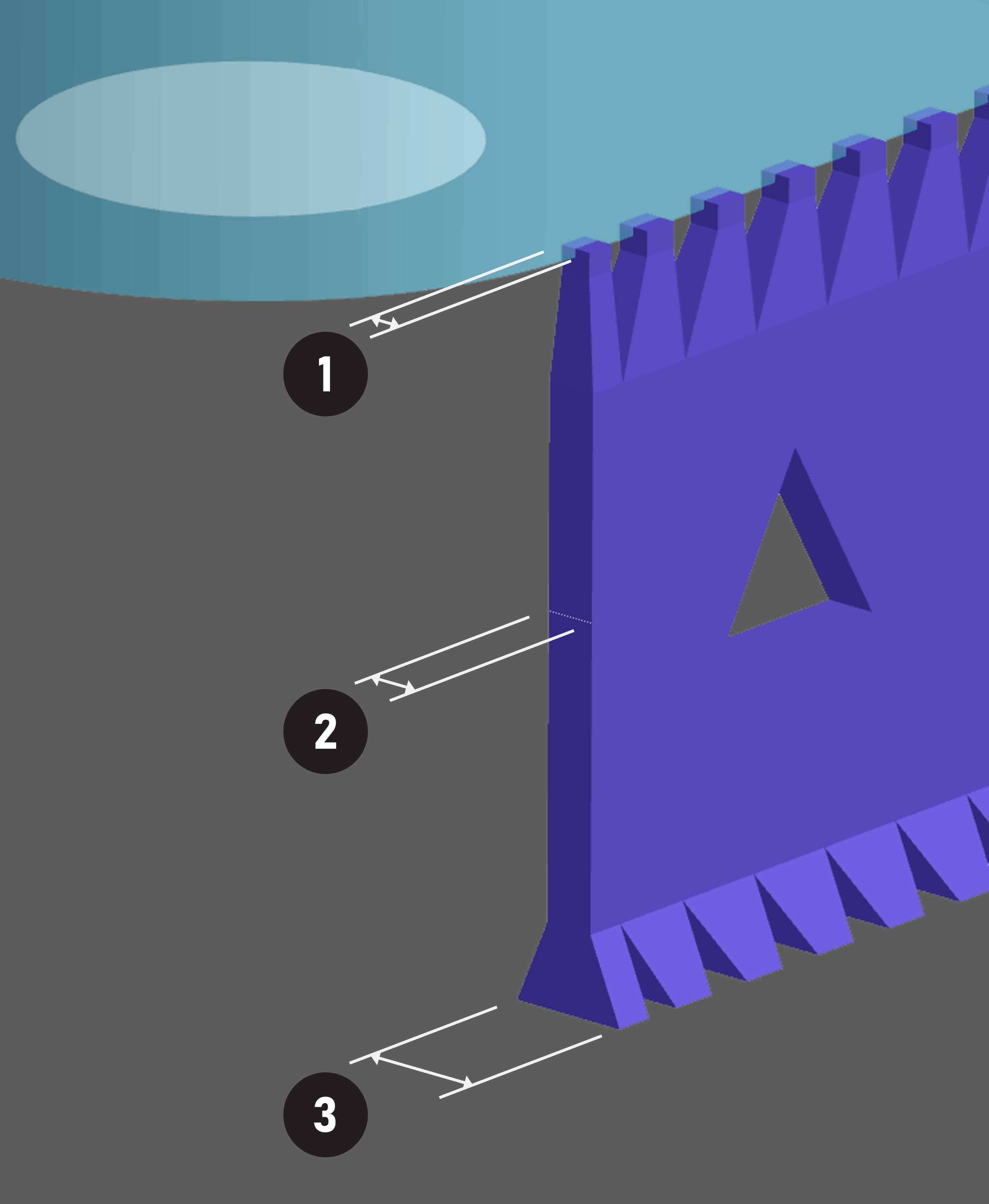
1. **Tip Thickness**
Thickness at the top of the support.
*This dimension may be fully or partially embedded in the part.*
2. **Wall Thickness\***
Main thickness for most of the fence support.
3. **Base Thickness**
Wider portion of the fence support that sits on the platform.
:::
:::VerticalSplitItem
**Bar Support Parameters**
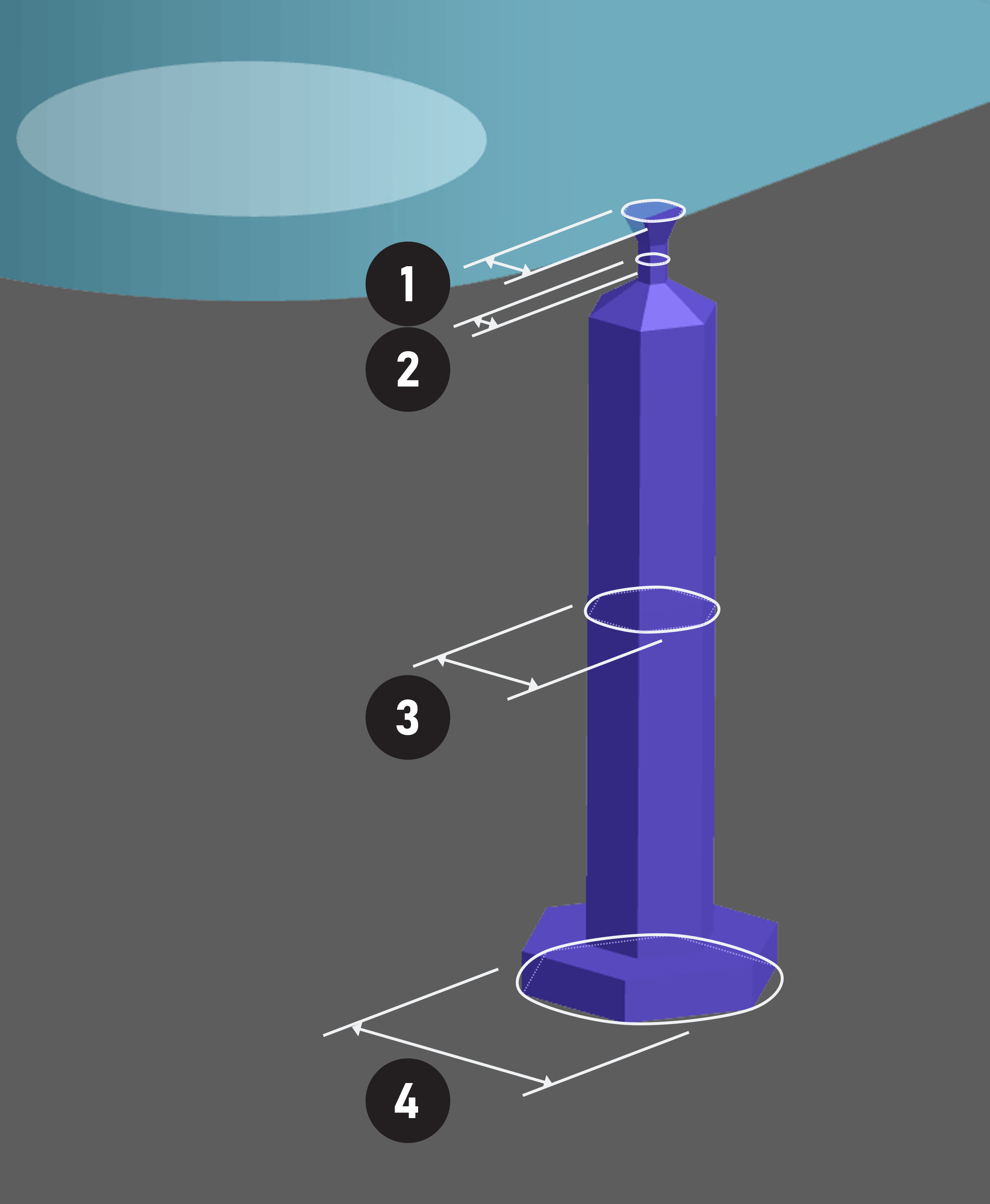
1. **Tip Diameter**
Diameter at the top of the support.
*This dimension may be fully or partially embedded in the part.*
2. **Neck Diameter**
Where the tip narrows as the break point.
3. **Bar Diameter\***
Main diameter for most of the support.
4. **Base Diameter\***
Wider part at the bottom of the support where it sits on the platform.
*By default, the base on a bar support is a multiplier of the bar diameter.*
*If you choose to specify a bar diameter but not a base diameter, the base diameter will be scaled up or down according to the bar diameter.*
:::
::::
:::hint{type="info"}
\* Guideline varies by height, and the most conservative guideline is shown.
:::
::::VerticalSplit{layout="middle"}
:::VerticalSplitItem

:::
:::VerticalSplitItem
**Default Parameters and Guidelines**
The default (auto) values for each parameter are pre-set for the resin you selected.
Those values are listed below the field as a guideline so you have a benchmark for increasing or decreasing values. When guidelines have an asterisk \*, the guideline varies by height, and the most conservative guideline is shown.
:::
::::
:::hint{type="warning"}
To use adjusted parameters, adjust the values **before** generating a support.
*Existing supports cannot be edited after generation but can be deleted.*
:::
**View Adjusted Parameters**
You may select any existing support to view the dimensional parameters associated with that support. *Software v1.43 and higher*
If multiple supports are selected that have different parameters, measurement fields will display “Multiple.” Select an individual support to see relevant dimensions.

:::hint{type="info"}
When existing supports are selected in the Print Preparation UI, parameters are grayed out/inactive to clarify that generated supports cannot be altered.
To modify support parameters, delete existing supports and re-generate.
:::
### Example Parameter Edits
***Tip/Neck - Decrease Tip Size***
*Example 1*
::::VerticalSplit{layout="left"}
:::VerticalSplitItem

:::
:::VerticalSplitItem
**Impeller on Bar Supports**
This part is printed raised on a bed of bar supports.
:::
::::
::::VerticalSplit{layout="left"}
:::VerticalSplitItem

:::
:::VerticalSplitItem
**Support Nubs Removed in Finishing**
All support nubs will be quickly sanded off the bottom surface as a finishing step.
:::
::::
::::VerticalSplit{layout="left"}
:::VerticalSplitItem

:::
:::VerticalSplitItem
**Tip Size Reduced on Edge**
An issue arises with the default tip size on supports close to an edge, where the tip size is large enough to leave material on both the bottom and side surface. Sanding the side surfaces would add a lot of time to the finishing step. To avoid additional finishing, the tip size can be reduced on these edge supports to eliminate support nubs from appearing on the side surface.
:::
::::
*Example 2*
Reducing the tip size could be used to better match feature sizes on the part. This threaded example uses fence supports on the edge of the thread. The default tip size wraps around the edge of the thread, while the smaller tip size stays confined to only the edge.
::::VerticalSplit{layout="middle"}
:::VerticalSplitItem

:::
:::VerticalSplitItem

:::
::::
*Example 3*
Reducing the tip on fence supports and both the tip and neck on bar supports, you can reduce the size of the support nubs left on the part. While results are visually subtle, this could have a favorable impact on finishing time in a production application.
*Note that the height of support nubs is not affected, only the thickness/diameter.*

:::hint{type="danger"}
**CAUTION**** -** Reducing tip/neck size too much can cause parts to detach during printing as seen in the example below. Utilize tip reduction with caution.
:::
***Tip/Neck - Increase Tip Size***
::::VerticalSplit{layout="middle"}
:::VerticalSplitItem

:::
:::VerticalSplitItem
**Part Detached from Supports During Printing**
Increasing the tip size can be a fix for parts that break away from supports during printing.
Parts that are top heavy and unstable, with relatively few supports at the beginning of the print, may benefit from supports having a stronger connection to the part to combat [suction forces](docId\:U7XYytjyDp3BvsYy2qKcU).
*See also **Base** parameter below.*
:::
::::
***Wall/Bar***
**Increasing** the wall thickness or bar diameter is a method to **improve stability** of a part during printing to combat [suction forces](docId\:U7XYytjyDp3BvsYy2qKcU). By default, bar supports already provide great stability, but fence supports provide little to no stability when tall.
In this example, the tall supports are required for stability only.

::::VerticalSplit{layout="middle"}
:::VerticalSplitItem
**Fence Supports**
**1.**The **default** fence support is too thin at this height to provide stability, will likely buckle under its own weight, and the part **will fail**.
**2.****Increasing the wall thickness** of the fence to the [recommended wall thickness](docId\:t94PR-A-C0pIhY6LJsWk7) for the resin will create a successful print.
:::
:::VerticalSplitItem
**Bar Supports**
**1.**Bar supports are always a stable option with **default** parameters.
**2.**As bar supports are already stable, increasing bar diameter is less common, but could be pursued to **reduce the overall quantity **of supports. In this example, a single bar support is used with an **increased bar diameter**. For this strategy to work, the **tip and neck diameter **also need to be **increased **to have a stronger connection to the part.
:::
::::
***Base***
If the wall thickness or bar diameter has been increased, the base often should be increased as well to remain larger than the support.
Note that fence supports and bar supports behave differently in the software when determining the base size.
- **Fence** base thickness is a **static **number
- To increase the base size to proportionally scale with the wall thickness, you must enter a higher value
- **Bar** base diameter is determined by a **multiplier **of the bar diameter
- A larger bar diameter will automatically scale up the base proportionally
- If the base scales up more than you prefer, enter a value
::::VerticalSplit{layout="middle"}
:::VerticalSplitItem
**Fence Support Base**

1. Default wall thickness and base
2. Increased wall thickness and default base
3. Increased wall thickness and increased base
:::
:::VerticalSplitItem
**Bar Support Base**

1. Default bar diameter and base
2. Increased bar diameter and default base (increased proportionally by default)
3. Increased bar diameter and increased base (manually increased)
:::
::::
::::VerticalSplit{layout="middle"}
:::VerticalSplitItem

:::
:::VerticalSplitItem
**Base Adhesion**
For parts highly susceptible to [suction forces](docId\:U7XYytjyDp3BvsYy2qKcU), the support itself may [under-adhere](docId\:DAbqNXb4KnG1eeiClRzqF) to the platform. **Increasing the base** will mitigate this failure.
This is especially true if you have increased the tip size of the support to hold onto the part more strongly. Usually, the part will detach from supports first, but if that connection is made stronger, the base may also need to be increased in size.
:::
::::
# Auto Supports
::::VerticalSplit{layout="middle"}
:::VerticalSplitItem
**When to Use**
Auto support is best used as a tool to provide guidance for **quoting**.
Auto Supports provide a quick approximation of how many supports will be needed via **Part and support volume **estimates in the Project Analysis tab.
:::
:::VerticalSplitItem

:::
::::
:::hint{type="info"}
The Average run time is **a few minutes**.
:::
**When ****NOT**** to Use**
Auto Supports utilize **overhang** and** island** information to inform where supports may be needed.
:::hint{type="danger"}
Printing forces are not considered in the algorithmic solution. **Adhesion** and **stability** are therefore not fully accounted for and print success with auto supports may vary.
:::
::::VerticalSplit{layout="middle"}
:::VerticalSplitItem
**Extra supports**

Due to how the algorithm assesses overhangs, it is not uncommon for Auto Supports to add small supports that are either difficult to access for removal and/or add minimal benefit. (Examples of extra supports shown here in red.)
:::
:::VerticalSplitItem
**Under-supported**

Auto Supports may not fully account for adhesion and stability. This example shows a manually supported solution that has a greater density of supports in key areas for adhesion and stability.
:::
::::
**Auto Supports are Resin Specific**
::::VerticalSplit{layout="middle"}
:::VerticalSplitItem

:::
:::VerticalSplitItem
The supports generated are specific for the selected resin.
For example RPU 70 will not have the same results as EPU 40. In the example shown here, you can see that the EPU 40 version has a greater quantity of supports (due to EPU 40 being softer during printing).
The elastomeric resins and MPU 100 tend to show the greatest variation from other resins.
:::
::::
**How Auto Supports Adapt to the Resin**
- Break points are sized for the resin
- Density of supports suit the resin
- Quantity of supports suit the resin
**How to Use Auto Supports**
::::::WorkflowBlock
:::WorkflowBlockItem
Select the **Automatic** tab for *quick iterations*, then click **Generate**.

:::
:::::WorkflowBlockItem
**Run on a Single Part**
::::VerticalSplit{layout="middle"}
:::VerticalSplitItem
The software will not allow you to select more than one part. Lay out the full build after supports are generated.
:::
:::VerticalSplitItem

:::
::::
:::::
::::::