Point Cloud
The Point Cloud feature translates data into lattice parameters.
Data Driven Lattices
Any data set that can be mapped to XYZ coordinates can utilize the Point Cloud feature. The goal is to correlate lattice parameters with the data to create variation across the lattice. Variation may be desired for multiple reasons: performance, adaptivity (conforming to changes in geometry), or even aesthetics.
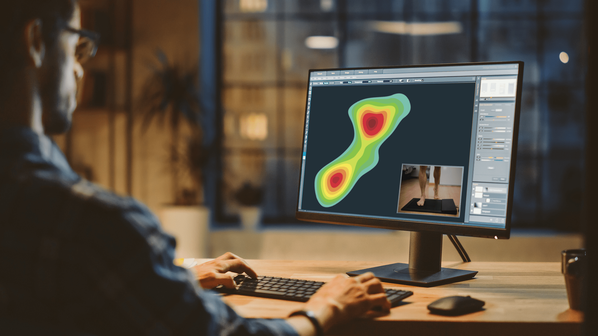
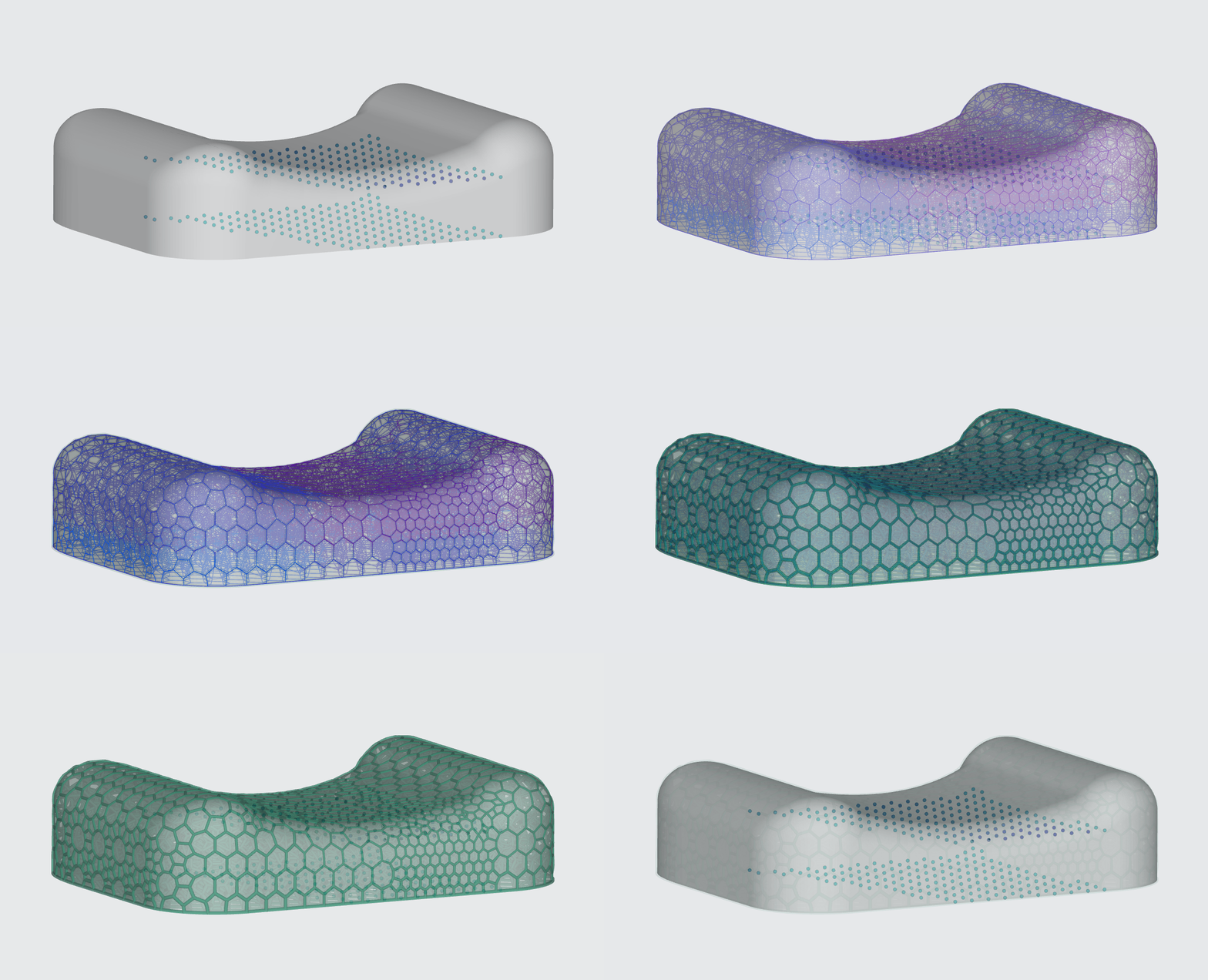
One common use case is to use pressure sensor data to define your lattice, utilizing personalized or aggregated data to build your applications as in the example below.
Point Cloud Workflow
CSV File
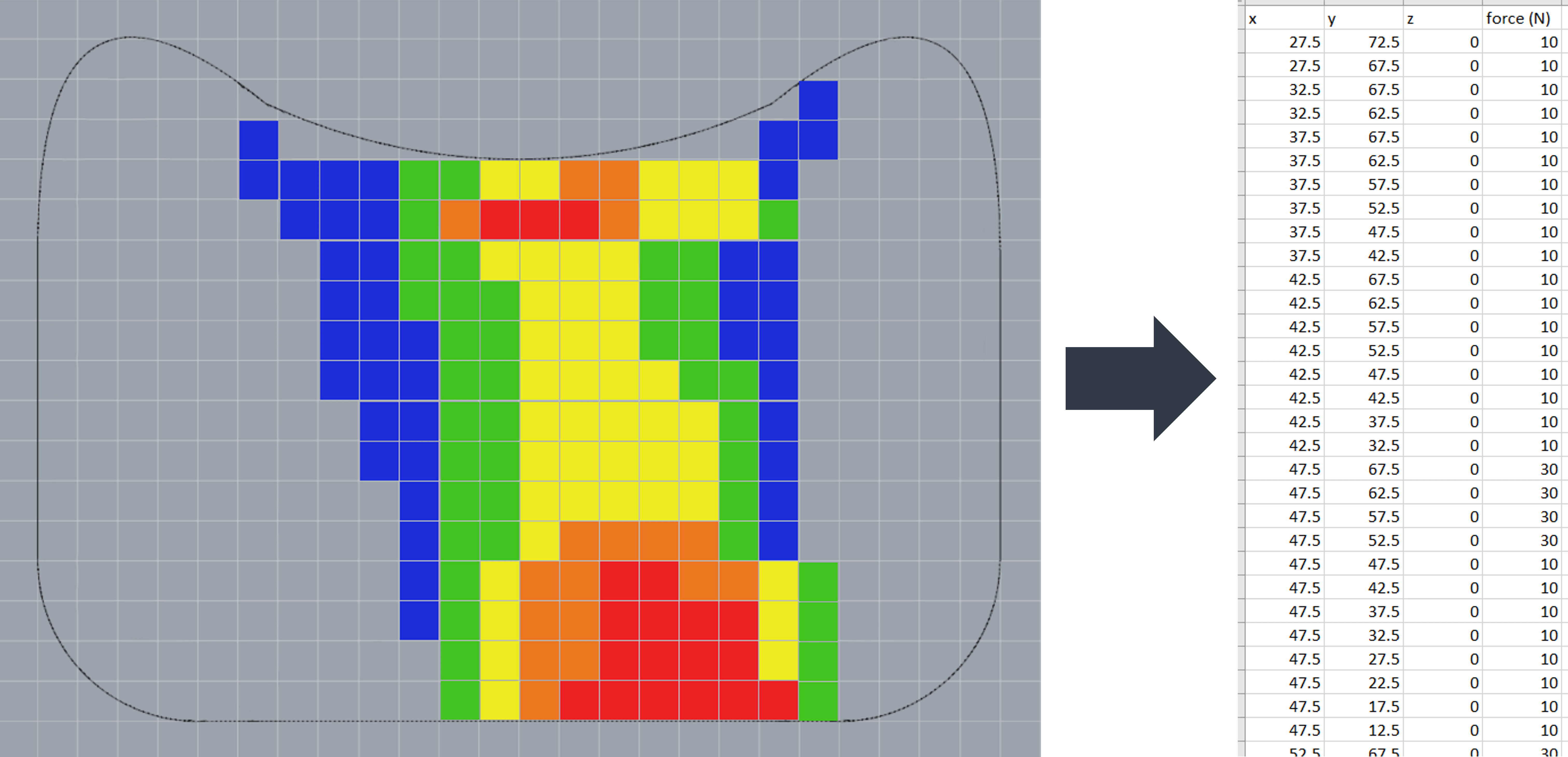
The data set must be converted to a CSV, formatted for Design Engine.
Alternate file types are not supported at this time (.doc, .xlsx, .png, etc.).

- After uploading a CSV, the file appears in the dropdown list under Mappings
- Users can upload multiple CSV files - all files appear in the dropdown
- Users can only select one CSV at a time

Model Location
Ensure that the input model is in the same world coordinate location as the data set coordinates. This can be done in your CAD file or with the Translate tool within the Design Engine (as shown here).

Point Mappings
Enter data from the fourth column of your CSV file as the input value and map that value to lattice parameters.
Mapping Basics
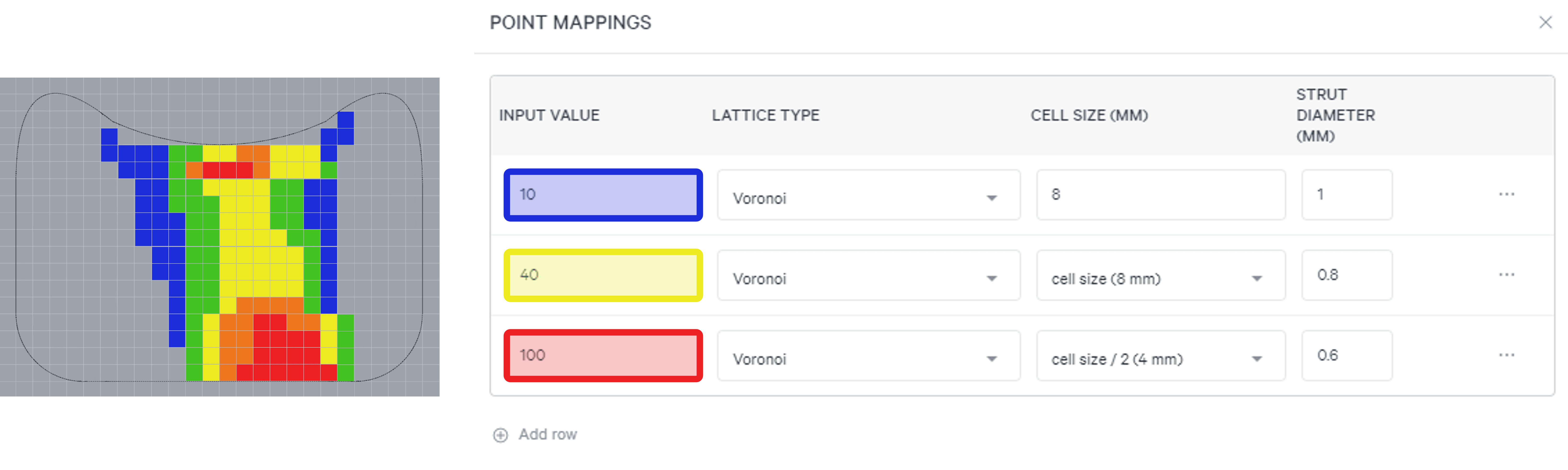
Non-mapped areas in the design space will take on the parameters of the nearest defined point (blue, yellow and red in this example)
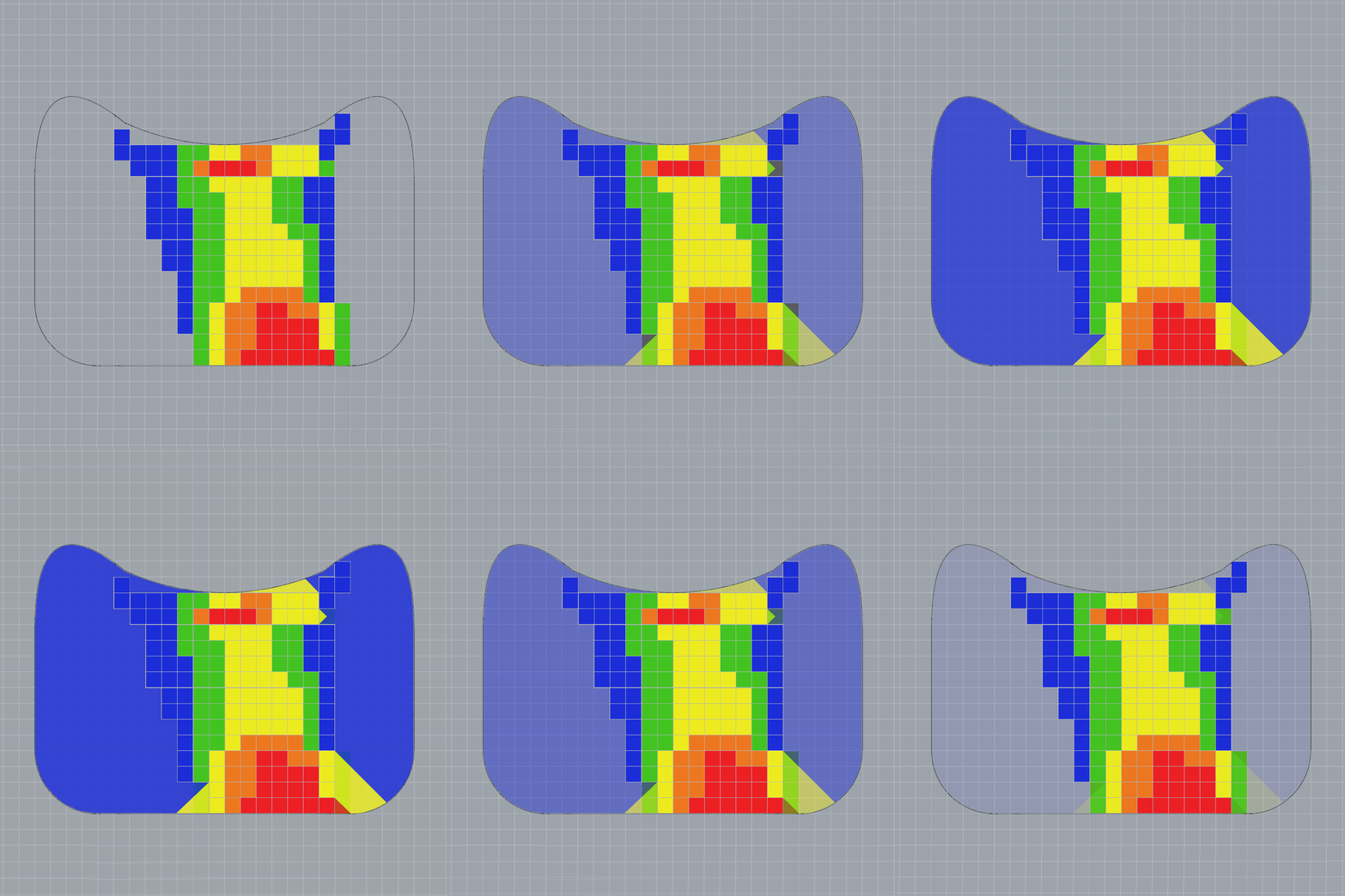

Enter a minimum of 2 rows for variation across your lattice - all values in between will be linearly interpolated (a single row will create a uniform lattice)

Enter more rows/data points for greater granularity
Cell Size - Factor of 2
- All cell size inputs must be based on a factor of 2 relative to the top row's cell size
- All viable options for rows 2 and beyond are listed in a drop-down menu
- Options that exceed 25 mm will be grayed out
- If the top row value is changed to make another row's selection larger than recommended (ie exceeds 25 mm), the lattice will generate, but it is recommended to review the results for production viability

Z Coordinate
- If data points are 2-dimensional, use a zero value for the Z coordinate
- Multiple Z coordinates can be used if data is 3-dimensional, or if different lattice parameters are desired in the Z axis
- This example places points at Z-zero and points at Z-16 (mm)
- The Z-zero points have lower input values than the points just below the design space surface in this example
- The resulting lattice uses thicker struts for the Z-zero points to give the lattice a stiffer base
Point Cloud Details
- Point cloud visibility and details can be accessed in the sidebar
- Standard menu options are available
- Hover over points to see input value
