---
title: Hex Mesh
slug: software/hex-mesh
description: Carbon Design Engine offers multiple options to create a hex mesh, which is one type of 3-dimensional scaffold structure for a lattice.
docTags:
createdAt: 2024-06-06T00:05:50.163Z
---
Every lattice begins with a mesh, which is the **underlying 3-dimensional scaffold** upon which your lattice is built. The mesh is comprised of **unit cells** upon which the strut lattice is applied.
Design Engine offers two mesh types: **Hexahedron Mesh** (Hex) and **Tetrahedron Mesh** (Tet).
A hex mesh is composed of polyhedrons with 6 faces and is best used when a **regular pattern and aesthetics** of the lattice are most important. This lesson walks through all the options to create a hexahedron mesh (hex) for the lattice's 3-dimensional scaffold.
:::hint{type="info"}
If you have not yet read about [hexahedron vs tetrahedron meshes](docId\:f-f8ROxDabcRrBEUDh6Q1) or the [hex lattice types](docId\:f-f8ROxDabcRrBEUDh6Q1) available for each, please do so before proceeding.
:::
Jump to Section:
- [How to Create a Hex Mesh](docId:2s1MLNX3Yfvzt6F5Rge5h)
- [Hex Mesh Population Type](docId:2s1MLNX3Yfvzt6F5Rge5h)
- [Gridded](docId:2s1MLNX3Yfvzt6F5Rge5h)
- [Loft](docId:2s1MLNX3Yfvzt6F5Rge5h)
- [Hex Lattice Types](docId:2s1MLNX3Yfvzt6F5Rge5h)
- [Custom Unit Cells](docId:2s1MLNX3Yfvzt6F5Rge5h)
# How to Create a Hex Mesh
Both mesh types require use of the [Strut Lattice](docId\:IDhmaxmVU97UzzIHV0Pdk) operation to populate the unit cell with struts. The difference between using tet vs hex mesh in Design Engine is in the steps needed to generate the strut lattice.
::::VerticalSplit{layout="middle"}
:::VerticalSplitItem
***Tet Strut Lattice Steps***
The strut lattice operation implicitly creates a tet mesh while creating the tet strut lattice.
1. [Strut Lattice](docId\:IDhmaxmVU97UzzIHV0Pdk)
2. [Solidify](docId\:pCwFrPen5GnTNB9INmFIB)
:::
:::VerticalSplitItem
***Hex Strut Lattice Steps***
Hex strut lattices require a separate operation to create a hex mesh scaffold first.
1. [Hex Mesh](docId:2s1MLNX3Yfvzt6F5Rge5h)
2. [Strut Lattice](docId\:IDhmaxmVU97UzzIHV0Pdk)
3. [Solidify](docId\:pCwFrPen5GnTNB9INmFIB)
:::
::::
::::VerticalSplit{layout="middle"}
:::VerticalSplitItem

:::
:::VerticalSplitItem

:::
::::
:::hint{type="warning"}
All strut lattices need to use the Solidify operation to be converted into a printable mesh file.
:::
# Hex Mesh Population Type
There are two methods for generating a hex mesh:
- **Gridded **- Constructed from rectangular cuboids, tiled to overlap the design space.
- **Loft **- Constructed by filling the design space between two parallel surfaces on the boundary of the input model. There are four methods available to construct the lofted hex mesh.
A general rule of thumb is to select the population type that most closely matches your geometry, but any method can be used to obtain desired results.
::::LinkArray
:::LinkArrayItem{headerType="IMAGE" headerImage="https://api.archbee.com/api/optimize/3CesIL2dYMCHPZvRjp8S0/In-JKcld75em5mkRXutYr_gridded-example-shape-ab.png"}
**Gridded**
:::
:::LinkArrayItem{headerType="IMAGE" headerImage="https://api.archbee.com/api/optimize/3CesIL2dYMCHPZvRjp8S0/KZIv6w08CpYihLot1cOt-_sectioned-example-shape-ab.png"}
**Loft - Sectioned**
:::
:::LinkArrayItem{headerType="IMAGE" headerImage="https://api.archbee.com/api/optimize/3CesIL2dYMCHPZvRjp8S0/NAssMJf-vI9ZNrxmcPwkh_rectangular-example-shape-ab.png"}
**Loft - Rectangular**
:::
:::LinkArrayItem{headerType="IMAGE" headerImage="https://api.archbee.com/api/optimize/3CesIL2dYMCHPZvRjp8S0/-_wJxUbQFpaRaMGtQzCrI_triangular-example-shape-ab.png"}
**Loft - Triangular**
:::
:::LinkArrayItem{headerType="IMAGE" headerImage="https://api.archbee.com/api/optimize/3CesIL2dYMCHPZvRjp8S0/73bIc3Itlzg1Th00AQZQa_annular-example-shape-ab.png"}
**Loft - Annular**
:::
::::
:::hint{type="info"}
Note that hex meshes are adjustable; the examples here are just one way to fill the design space.
These examples use the Grid lattice type; more options are available for hex lattice types.
:::
# Gridded
Hex gridded is the simplest mesh structure that uses a cube, or **rectangular cuboid**, tiled to fully overlap the design space.
All hexahedrons on the boundary of the design are cropped to the intersecting shape, meaning that all boundary unit cells are a different size and shape than any full unit cells in the interior.
::embed[]{url="https://vimeo.com/830729722"}
:::ExpandableHeading
Video Text
1. Select Gridded
• Select Gridded hexahedron population type
• Select preview to visualize
2. Adjust cell size
• Rectangular cuboid is adjustable in X-Y-Z dimensions
• Preview regenerates after a few seconds of inactivity
3. Adjust alignment
• Adjust view to assess alignment
• Align the mesh as desired - centered by default
4. Generate Mesh
5. Generate Strut Lattice
:::
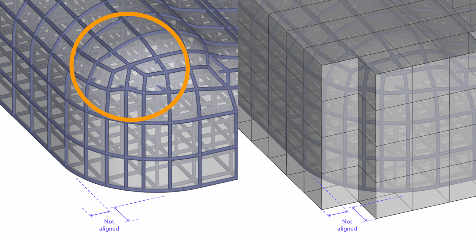
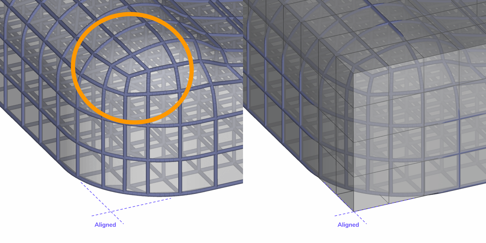
**Alignment Tip **- Best results divide the design space as evenly as possible. Hexahedrons that are cropped to less than half their original size will require shortened connections to conform to the design space, which can create an irregular pattern in those areas.
::::VerticalSplit{layout="middle"}
:::VerticalSplitItem
:::
:::VerticalSplitItem
:::
::::
:::hint{type="info"}
Complex compound curves may not properly conform to the design space with the gridded mesh structure. In these cases, the loft options are better solutions.
:::
# Loft
There are four types of loft hexahedral meshes, but the core concept behind them is the same. Lofted hex meshes are constructed by filling the design space between two parallel surfaces on the boundary of the input model. All hexahedrons throughout the mesh are morphed to fit into the design space. This creates a very regular pattern but results in unit cells that vary in size and shape throughout the design space.
::::VerticalSplit{layout="middle"}
:::VerticalSplitItem
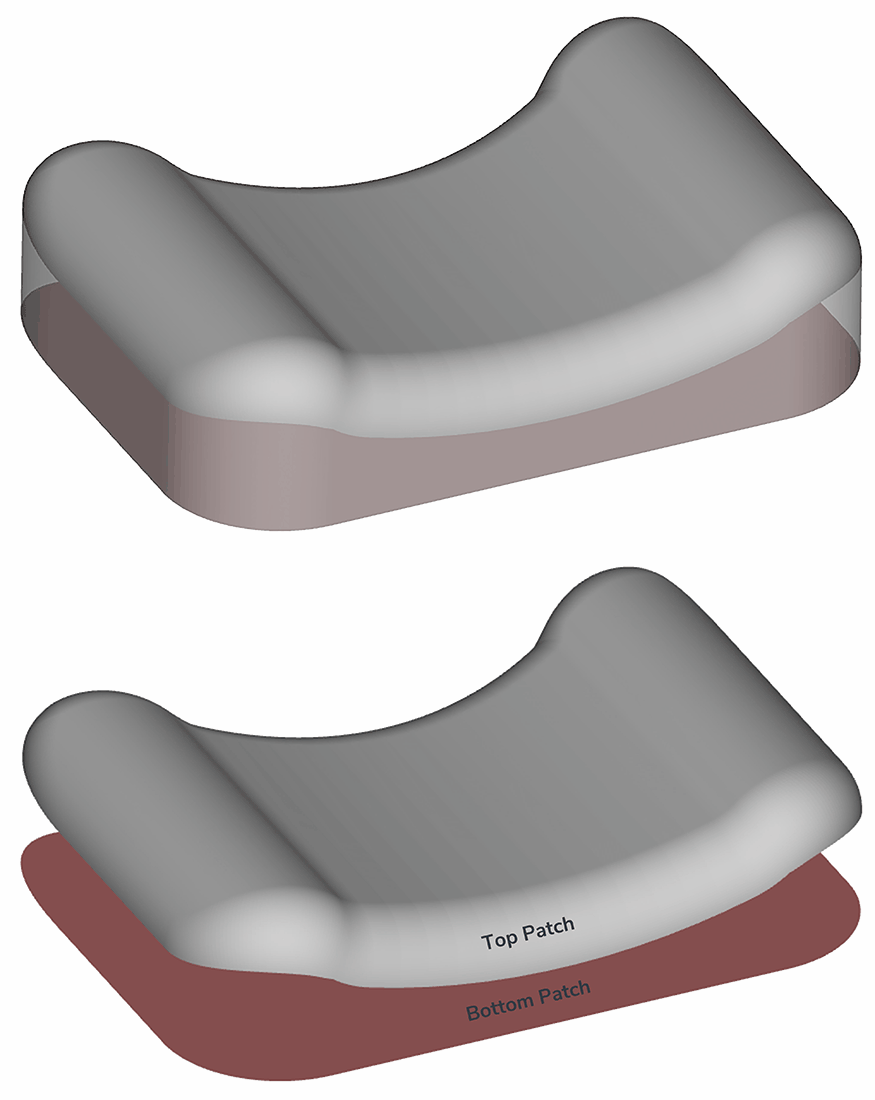
**Loft Patches**
This method requires additional inputs of parallel surface patches on your design space.
Reference the [Extract Patch](docId\:x7Oz62EQ1tqD2OXHY5ujD) lesson for details on selecting the surface patches.
:::
:::VerticalSplitItem
:::
::::
**Loft Workflow**
Shown with the triangular pattern, but all methods follow these basic steps.
::embed[]{url="https://vimeo.com/832100986"}
:::ExpandableHeading
-unhandled content type-
1. Select Loft
• Select Loft hexahedron population type
• Select population pattern
• Select start and end patch
• Select preview to visualize
2. Adjust cells
• Select cell divisions along path or axis
3. Adjust Reference Points
• Click Advanced
• Click and drag points to adjust population shape to your design space
• Enter exact coordinates for points as needed
4. Generate Mesh
5. Generate Strut Lattice
:::
## Loft Population Patterns
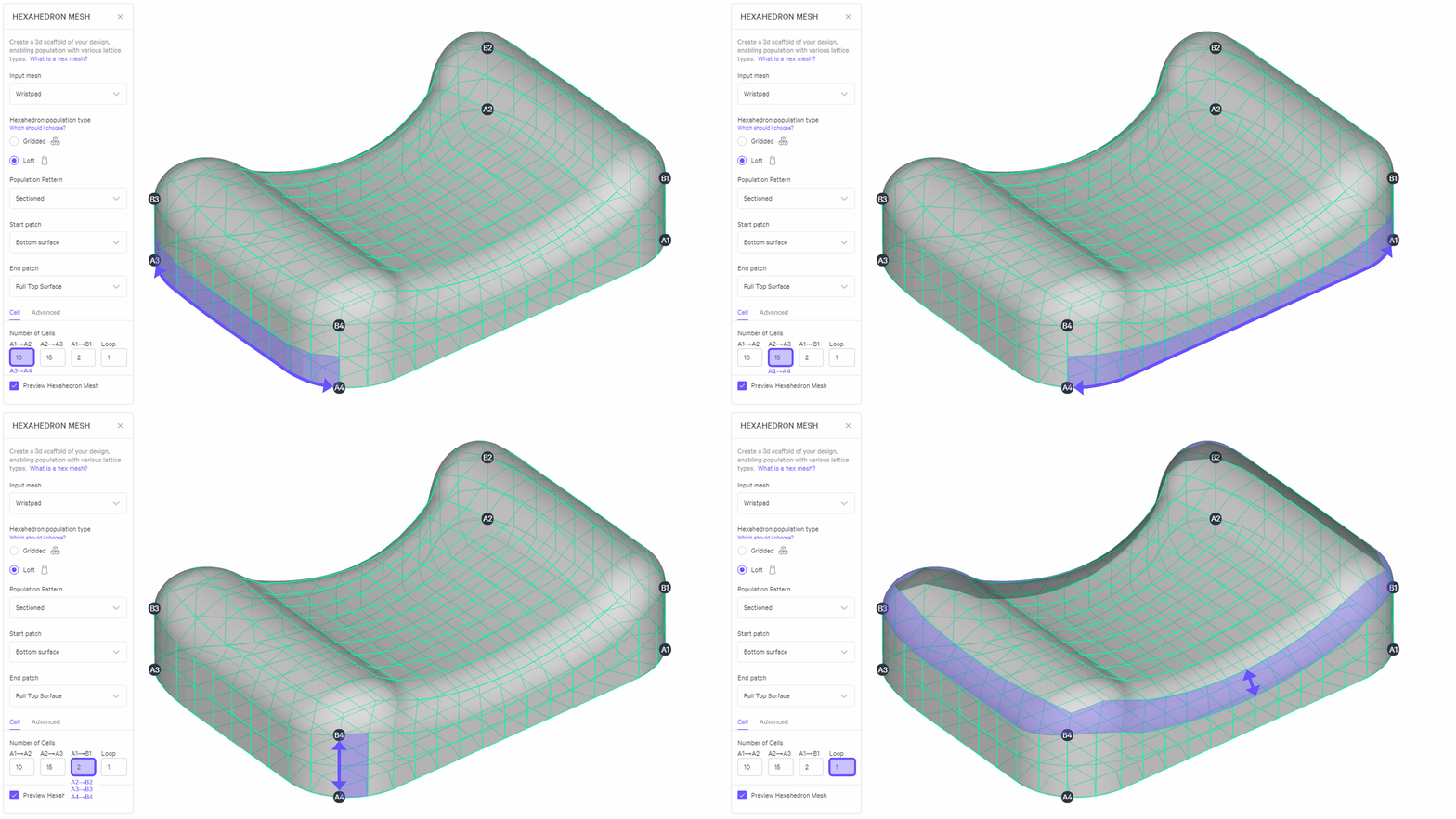
The loft methods are distinguished by their options, which are driven by their underlying shapes.
### Sectioned
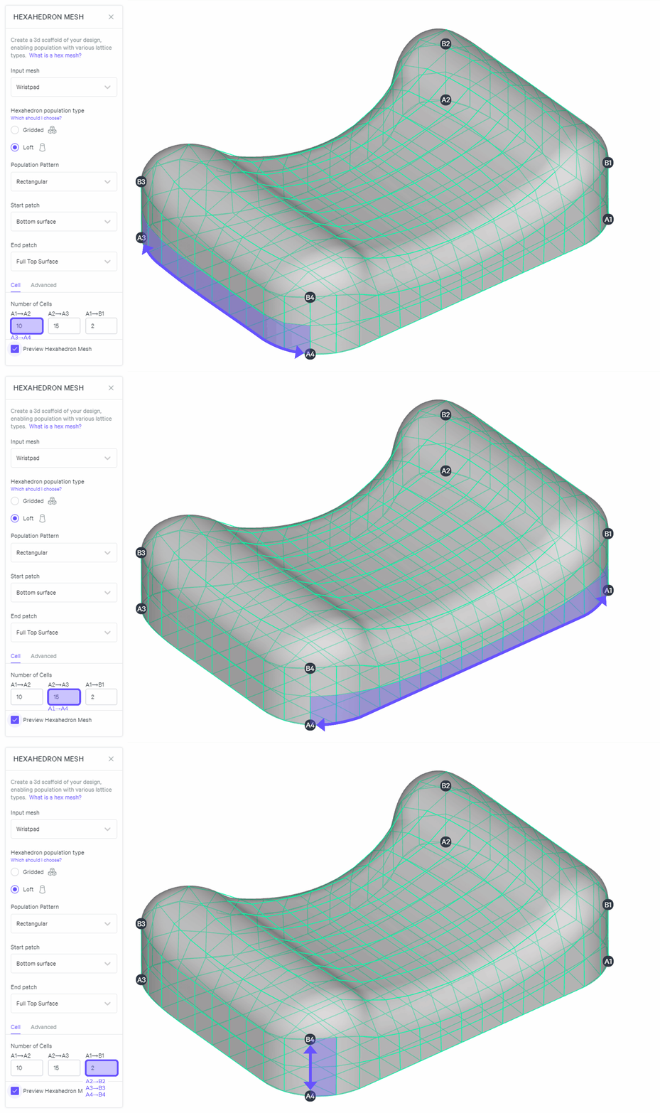
### Rectangular
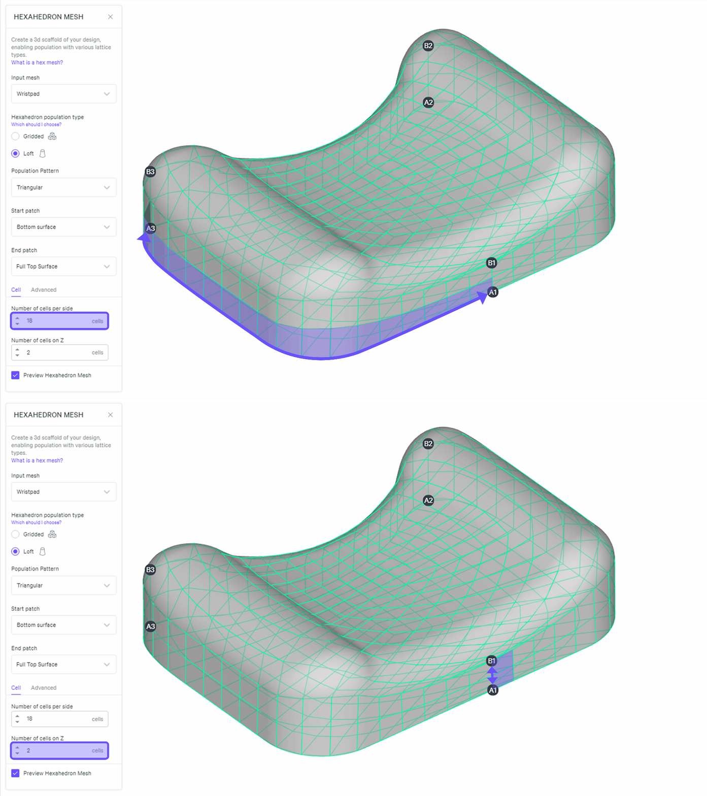
### Triangular
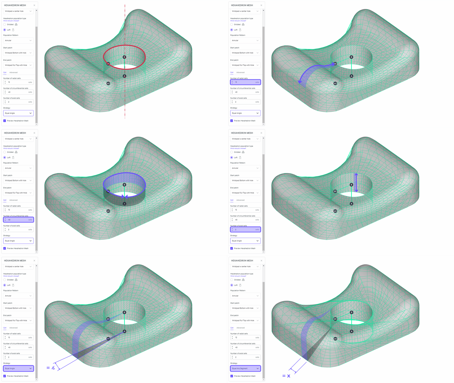
### Annular
:::hint{type="danger"}
**Design space must contain a hole.**
:::
## Notes for All Loft Methods
::::VerticalSplit{layout="middle"}
:::VerticalSplitItem
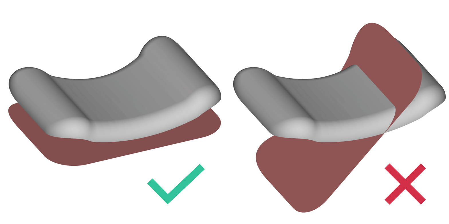
**Surface Patches**
:::
:::VerticalSplitItem
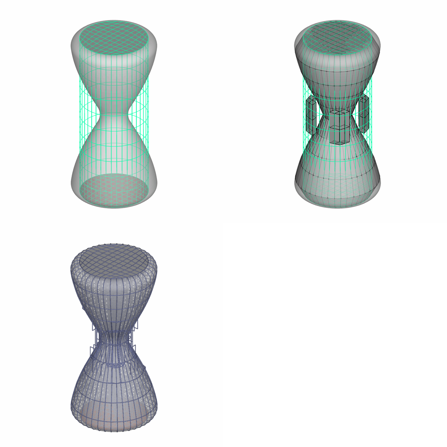
**Hourglass Shapes**
:::
::::
::::VerticalSplit{layout="middle"}
:::VerticalSplitItem
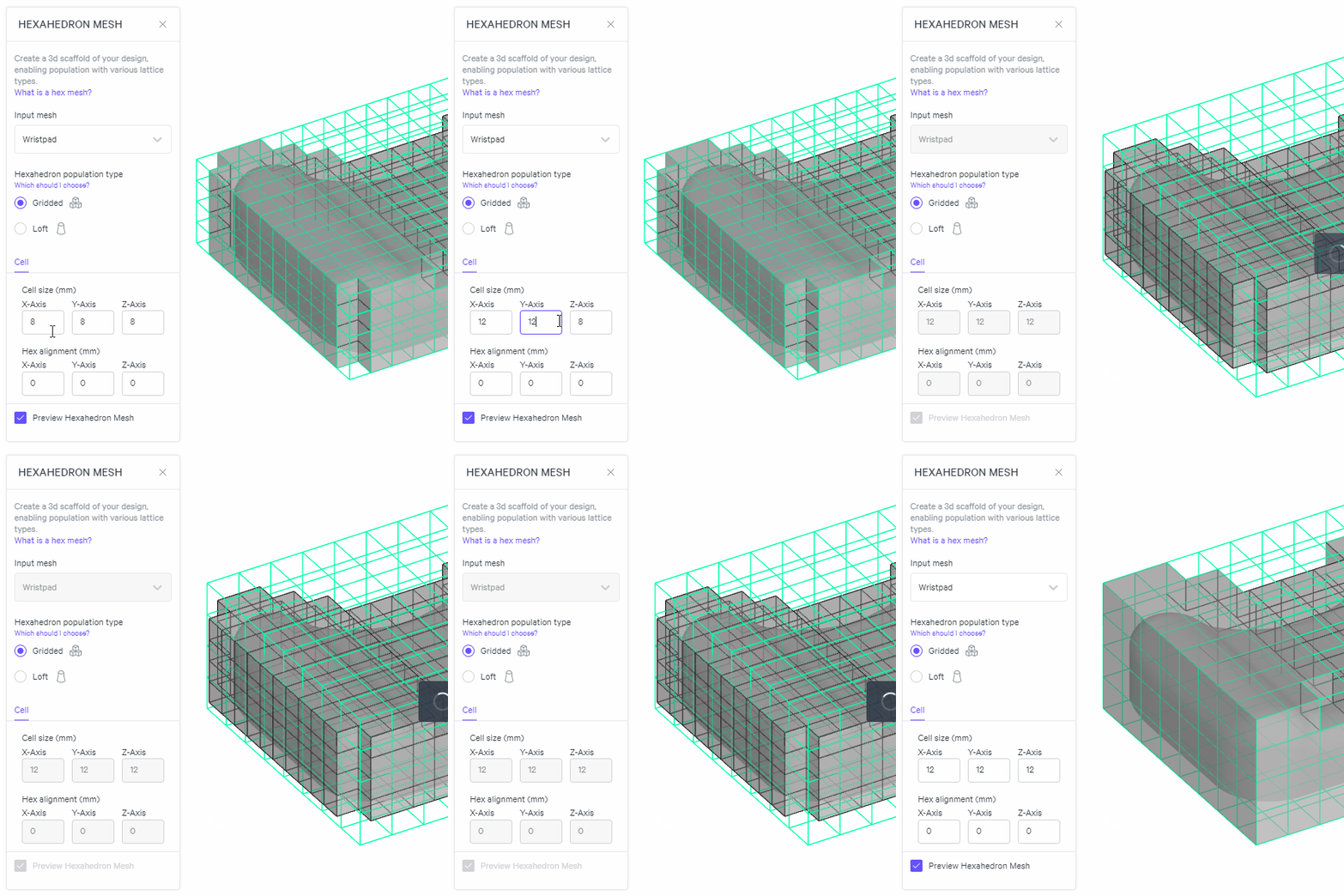
**Preview**
:::
:::VerticalSplitItem
**Surface Patch Files**

:::
::::
# Hex Lattice Types
Design Engine provides seven pre-defined hex lattice types.
Reference [Lattice Type Guidelines](docId\:f-f8ROxDabcRrBEUDh6Q1) for more information.
::::LinkArray
:::LinkArrayItem{headerType="IMAGE" headerImage="https://api.archbee.com/api/optimize/dptYqcTHPbVZhe3zuNg4v-qcoSlF-YWn9mE4zPQaOBy-20240925-193949.png"}
**Cross**
Medium % Volume Fraction
:::
:::LinkArrayItem{headerType="IMAGE" headerImage="https://api.archbee.com/api/optimize/dptYqcTHPbVZhe3zuNg4v-PuJvTN57DnOCiLRz53KkI-20240925-203208.png"}
**Fluo**
High % Volume Fraction
:::
:::LinkArrayItem{headerType="IMAGE" headerImage="https://api.archbee.com/api/optimize/dptYqcTHPbVZhe3zuNg4v-Xj_i5lytlK1jq0tkG5AbW-20240925-203228.png"}
**Grid**
Low % Volume Fraction
:::
:::LinkArrayItem{headerType="IMAGE" headerImage="https://api.archbee.com/api/optimize/dptYqcTHPbVZhe3zuNg4v-BdHFpA6yF-J8C2vxwfUMY-20240925-203245.png"}
**Kelvin** (Hex)
Medium % Volume Fraction
:::
:::LinkArrayItem{headerType="IMAGE" headerImage="https://api.archbee.com/api/optimize/dptYqcTHPbVZhe3zuNg4v-5cM7F4sCwGtB1lWDj21VC-20240925-203309.png"}
**Octahedral**
Medium % Volume Fraction
:::
:::LinkArrayItem{headerType="IMAGE" headerImage="https://api.archbee.com/api/optimize/dptYqcTHPbVZhe3zuNg4v-Ce2wOWQc0VDMrfTmNd1-7-20240925-203324.png"}
**Octet**
High % Volume Fraction
:::
:::LinkArrayItem{headerType="IMAGE" headerImage="https://api.archbee.com/api/optimize/dptYqcTHPbVZhe3zuNg4v-fnFoqDXXW4WnzA1MVvxW3-20240925-203337.png"}
**Star **(Hex)
Medium % Volume Fraction
:::
:::LinkArrayItem{headerType="IMAGE" headerImage="https://api.archbee.com/api/optimize/dptYqcTHPbVZhe3zuNg4v-VWSSpBH0KuUBCxpq8HK_e-20240925-203350.png"}
**Tesseract**
High % Volume Fraction
:::
::::
# Custom Unit Cells
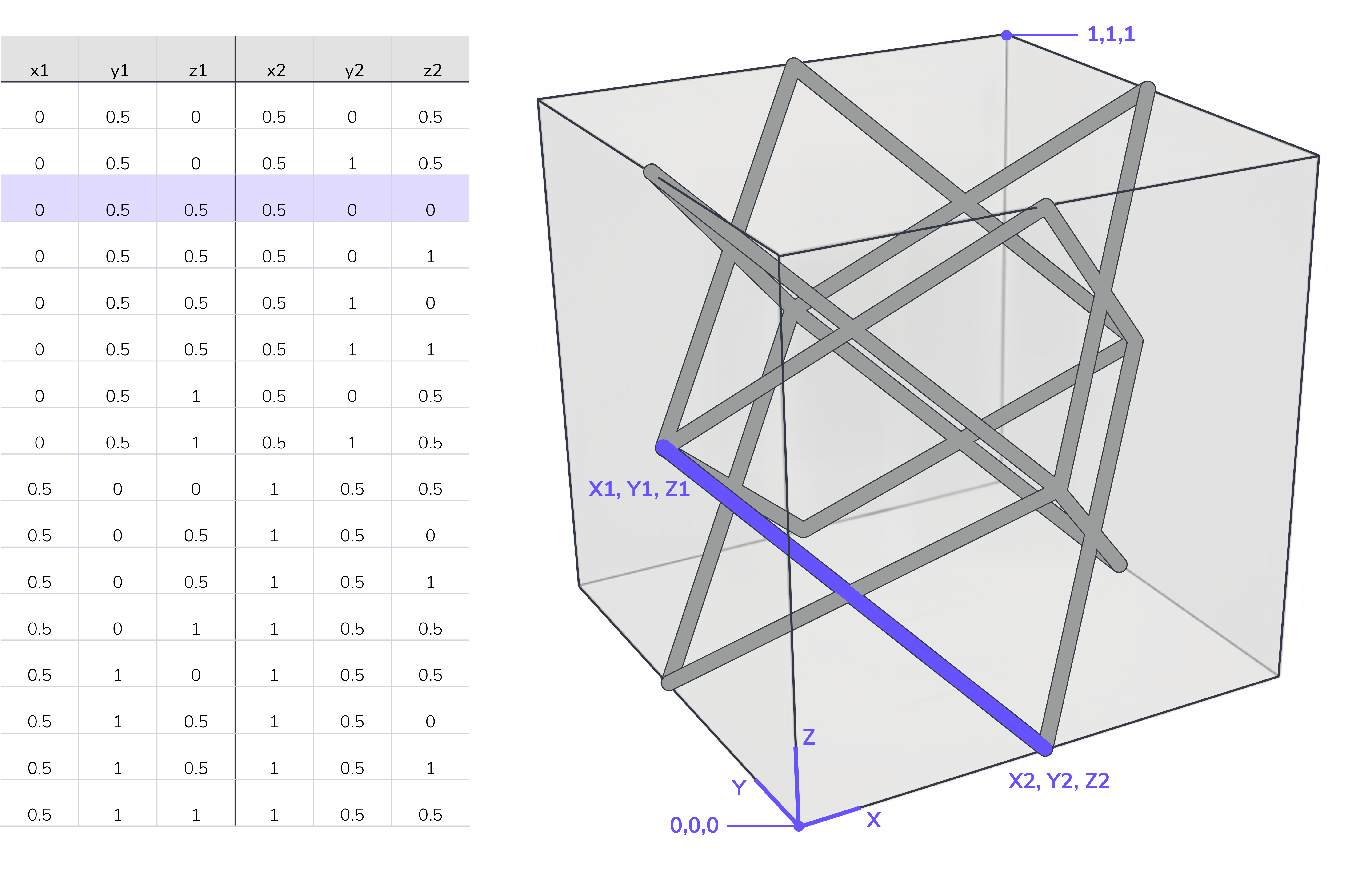
Design Engine allows you to define your own unique lattice type for hex meshes via an imported csv file.
- The csv should define the start and end nodes for each strut within the hexahedron.
- Nodes are defined by x1, y1, z1 and x2, y2, z2.
- The csv should include a header row labeled with x1, y1, z1, x2, y2, z2.
A blank csv file with the proper format is available for download below.
- Assume a unitless cube of 1 x 1 x 1 dimensions to define the nodes.
::File{src="https://api.archbee.com/api/presign/3CesIL2dYMCHPZvRjp8S0/ZVvJ5_6ocTNj49HdfdaYQ_csv-custom-hex.csv" label="CSV-Custom-Hex.csv"}
## Successful Unit Cell Guidelines
::::VerticalSplit{layout="left"}
:::VerticalSplitItem
**Tile 3-dimensionally **
Points in the two **X-X**, **Y-Y**, and **Z-Z** planes must have matching nodes.
:::
:::VerticalSplitItem
::Image[]{src="https://res.cloudinary.com/carbon3d/image/upload/v1718147063/Education/Software/Design-Engine/Tools-Features/Hex-mesh/Tiling-shaded-gif.gif" size="70" width="1080" height="1080" position="center" alt="Tile 3-dimensionally" showCaption="false"}
:::
::::
::::VerticalSplit{layout="left"}
:::VerticalSplitItem
**Connect at least 2 faces within the cube**
None of the struts in this example tie together faces of the cube. The resulting lattice may populate the design space but closer inspection from the side view shows that the lattice does not connect 3-dimensionally.
In extreme cases, the lattice may only populate with feature edges (when specified).
:::
:::VerticalSplitItem
::Image[]{src="https://res.cloudinary.com/carbon3d/image/upload/v1718147214/Education/Software/Design-Engine/Tools-Features/Hex-mesh/Custom-unit-cell-disonnected-v0101_sml.gif" size="70" width="540" height="540" position="center" alt="Connect at least 2 faces within the cube" showCaption="false"}
:::
::::
## Custom Unit Cell Surface Patterns
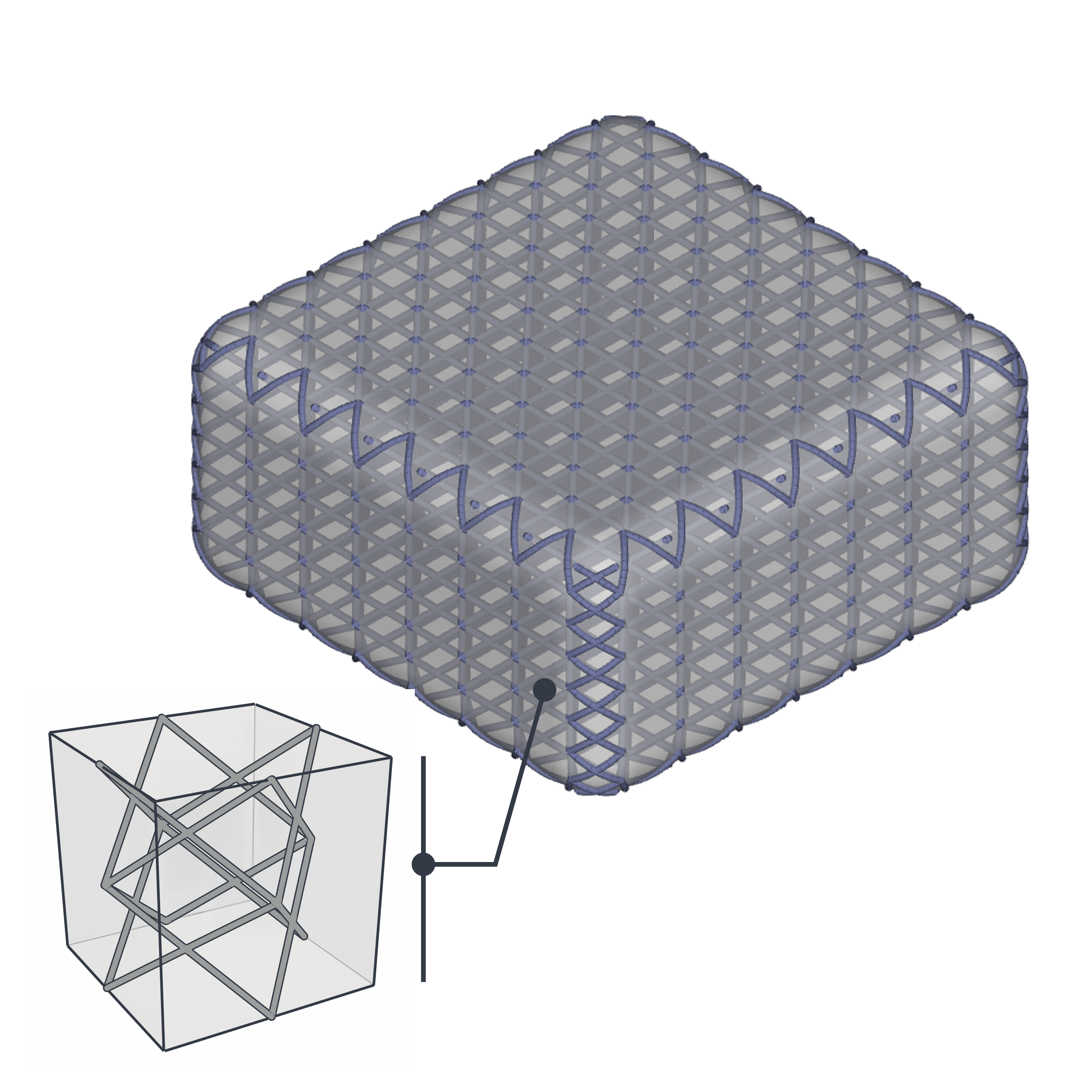
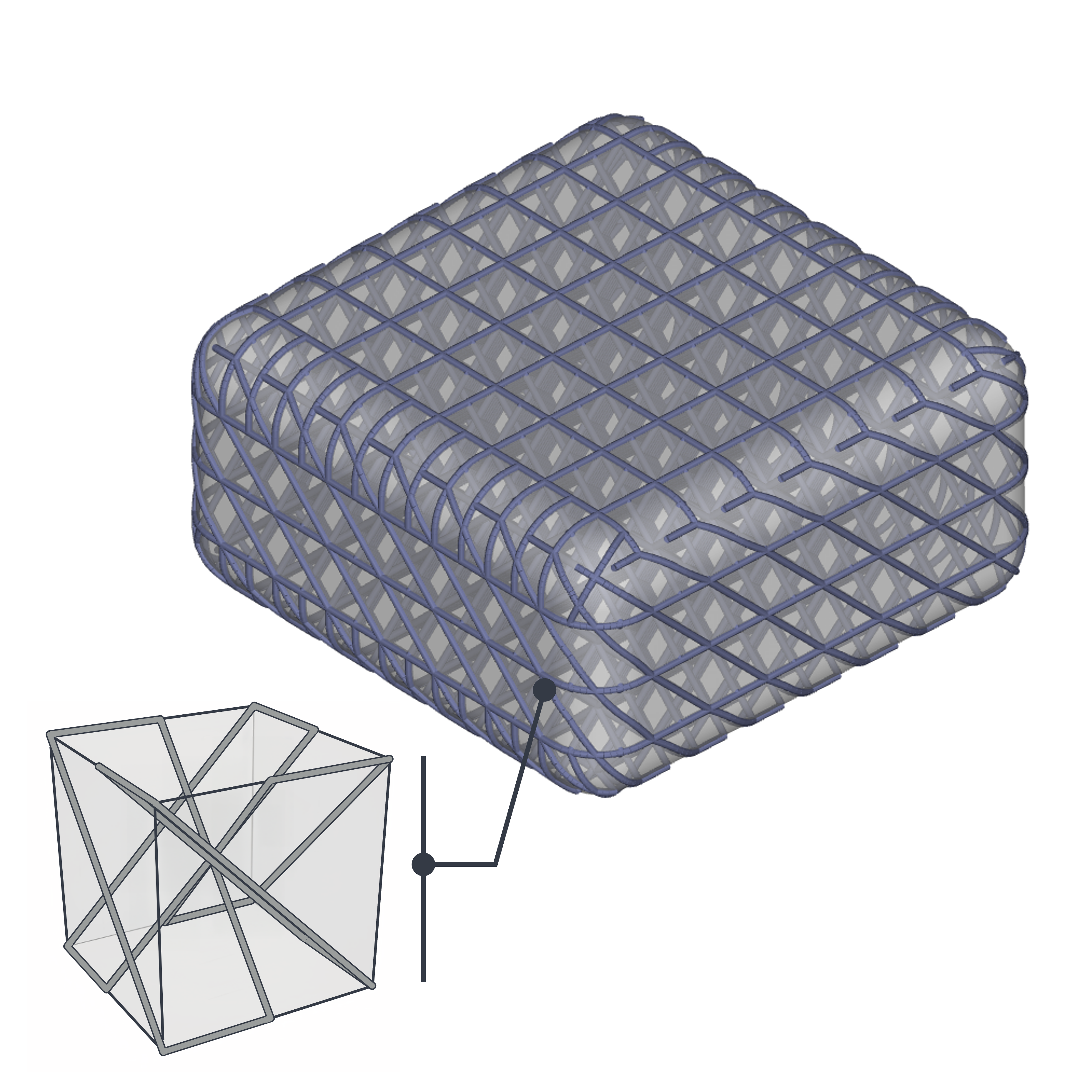
Surface patterns on custom unit cells will primarily follow how the struts interface with the faces of the hexahedron. Variations will occur at curves and other non-orthogonal geometries.
- **Example 1 - Nodes**
This example contains only nodes on the surface of the hexahedron. This manifests only nodes on most surfaces but varies where the geometry is non-orthogonal.
- **Example 2 - Edges**
This example contains struts along the faces of the hexahedron. This manifests a surface pattern of struts on most surfaces but varies where the geometry is non-orthogonal.
::::VerticalSplit{layout="middle"}
:::VerticalSplitItem
:::
:::VerticalSplitItem
:::
::::
:::hint{type="info"}
Custom unit cells are different than the pre-defined hex lattice types which always generate a surface pattern of struts. This is baked into the software on the backend. If you like one of the pre-defined hex types with only nodes on the surface but don't want the surface pattern, you could recreate it as a custom unit cell to eliminate the surface pattern.
:::