Navigation and Options
Design Engine User Interface
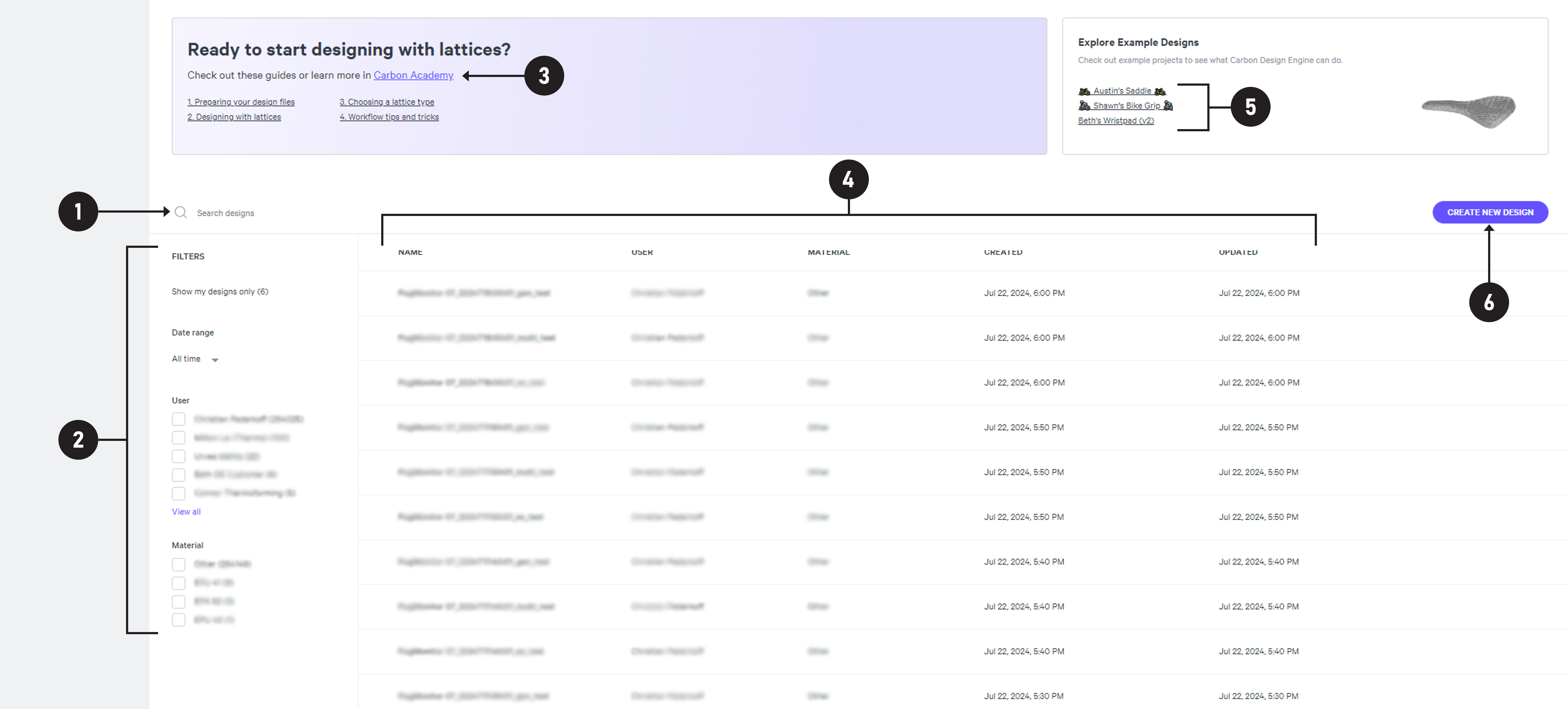
Dashboard UI
The dashboard is the landing page for the Design Engine and is the hub for all of your company's designs. Click on the name of a feature below for more information.

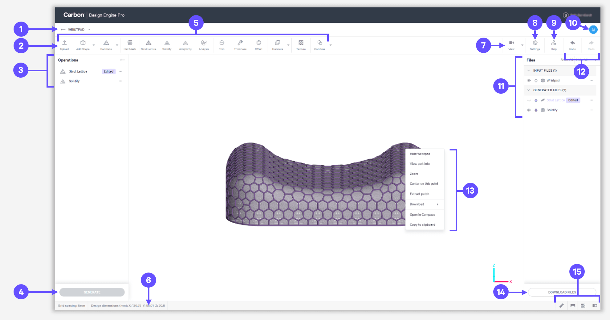
Design UI
The design page is the workspace for any given design project. Click on the name of a feature below for more information.

Bottom Bar Features
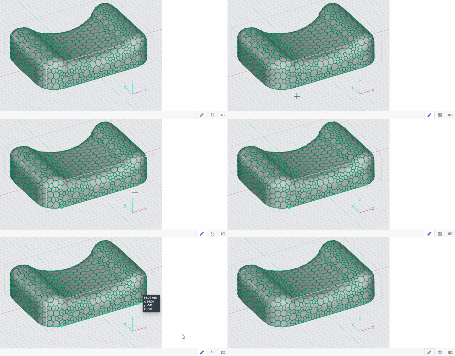


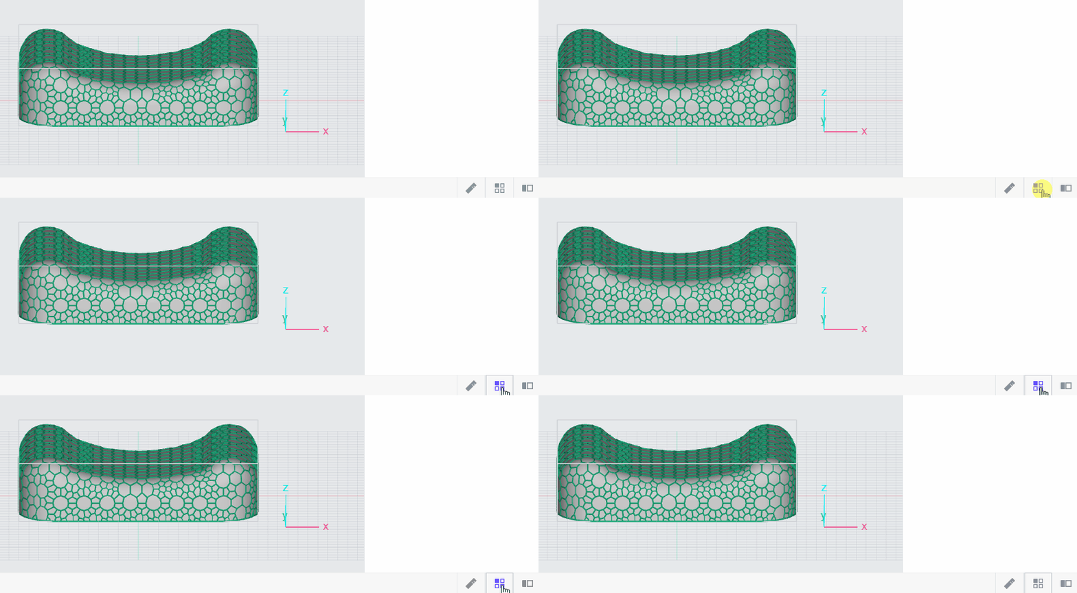
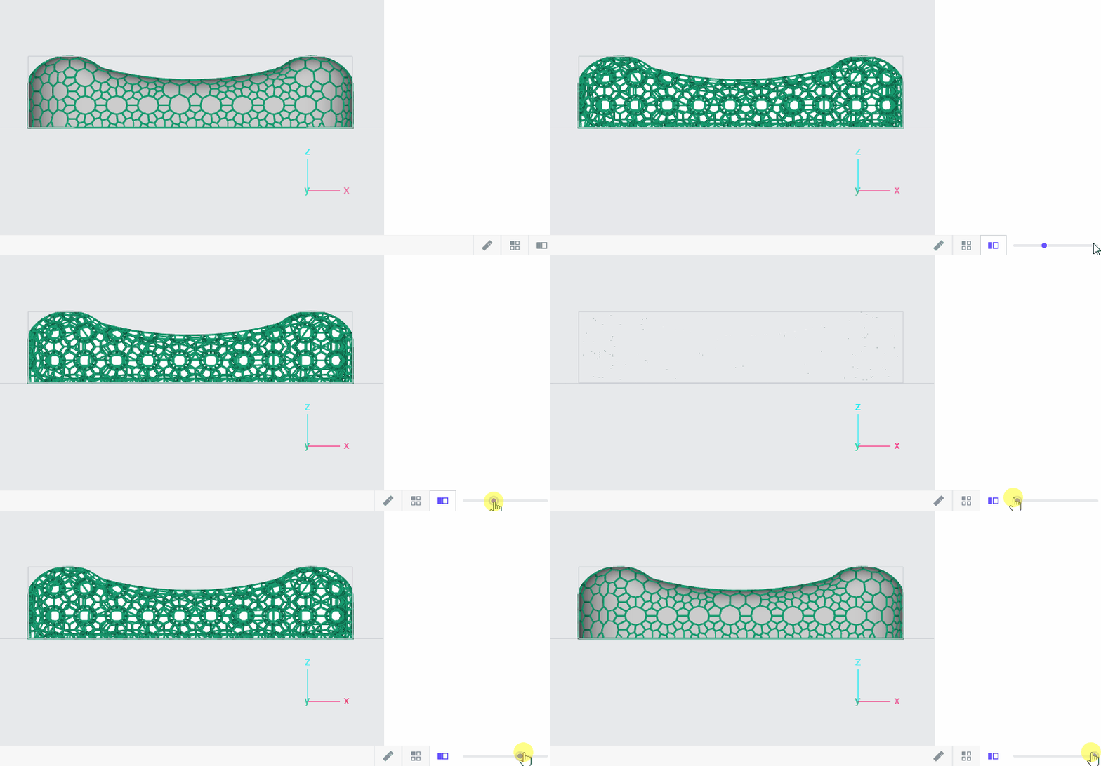
Navigation
Zoom
Zoom to Center
View always zooms to the center of the display screen (Default behavior)
Usage
- Mouse - Scroll the mouse wheel
- Touchpad - Drag two-fingers on the touchpad
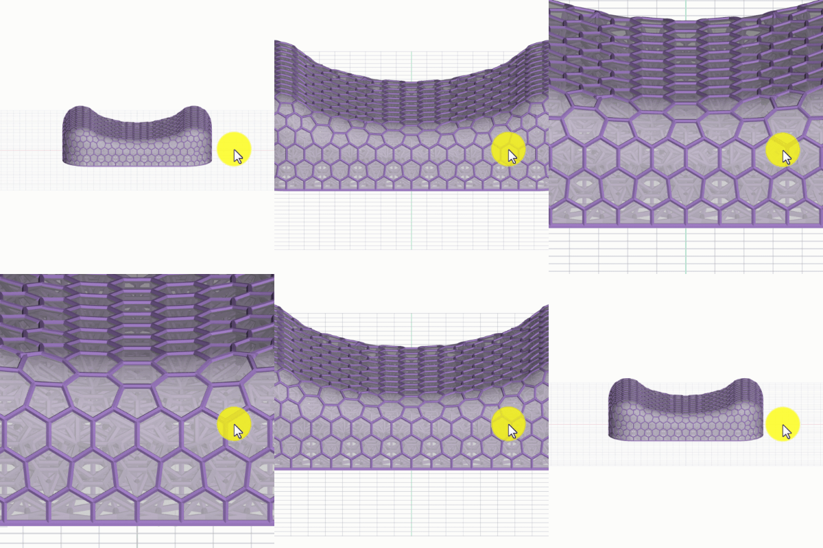
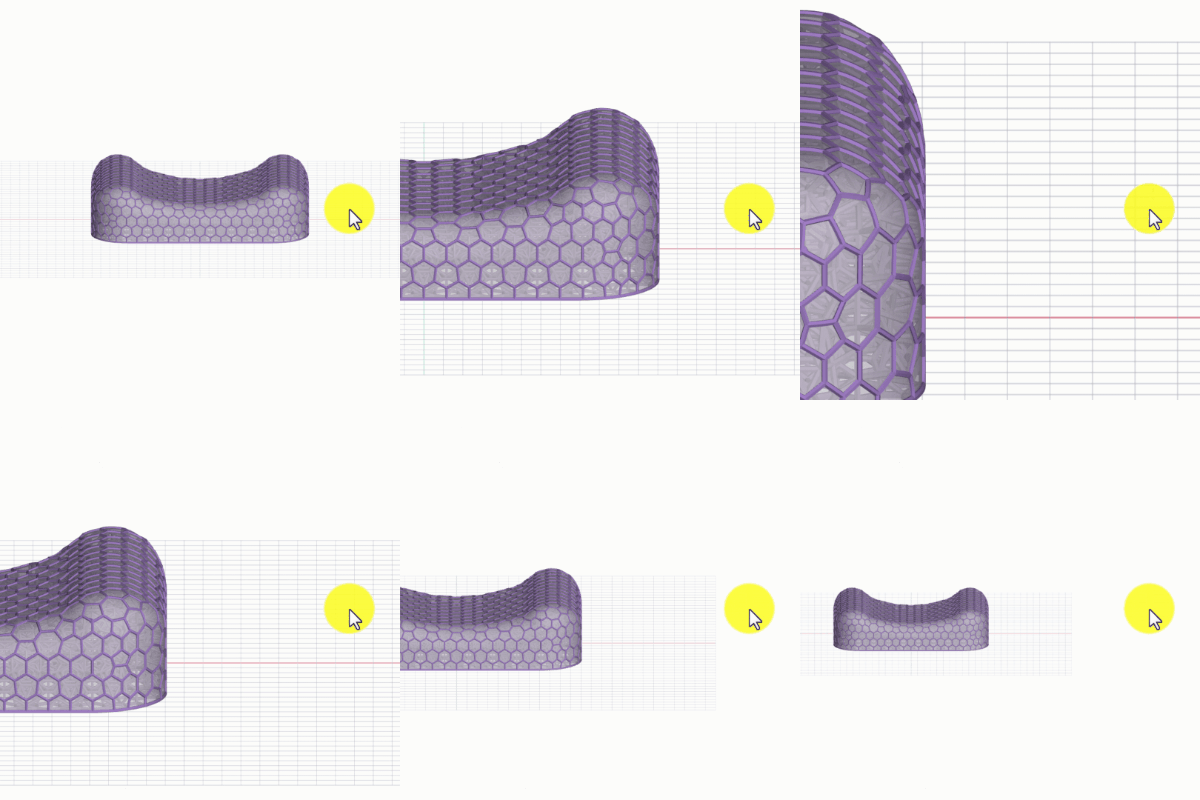
Zoom toward Cursor
View zooms/pans in one motion in the direction of the cursor placement
Press the keyboard shortcut - to enable/disable
Usage
- Mouse - Scroll the mouse wheel
- Touchpad - Drag two-fingers on the touchpad
Zoom to Fit
Zooms to the extents of the model and centers in the project area
Usage
- Keyboard shortcut F
- View Menu
- File Menu
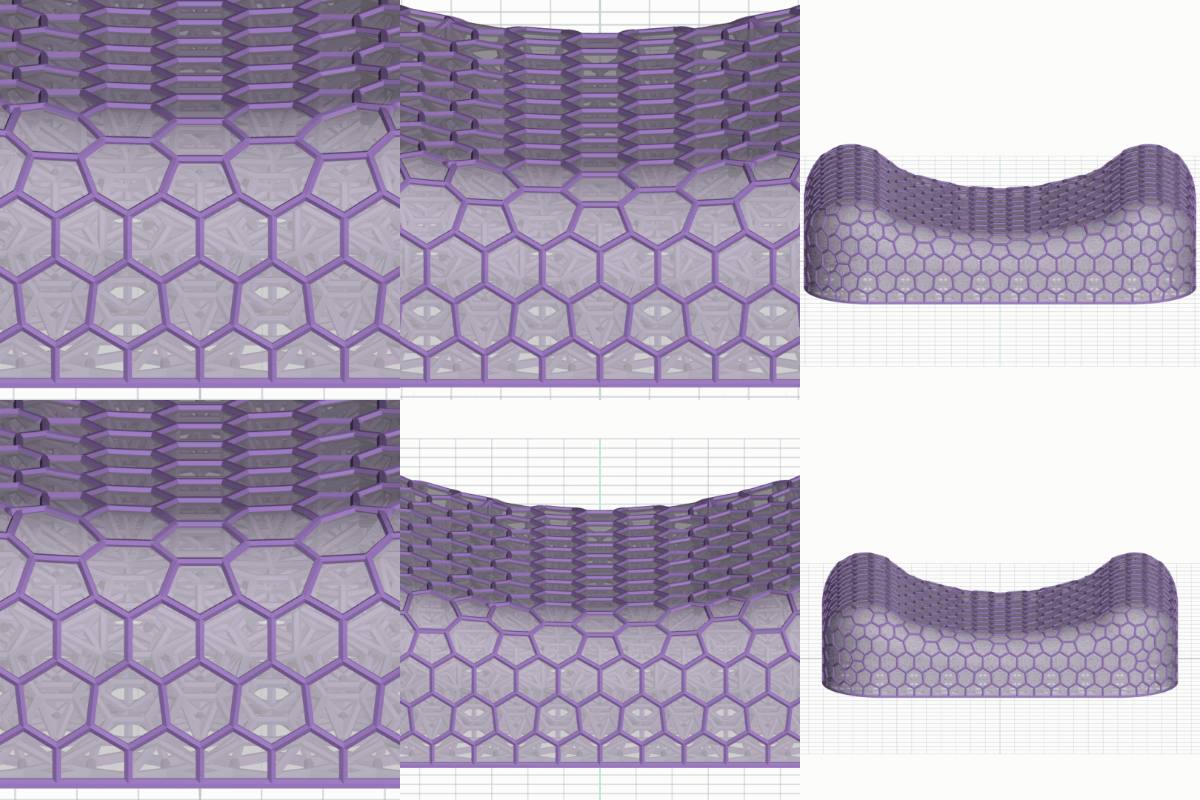
Maneuver
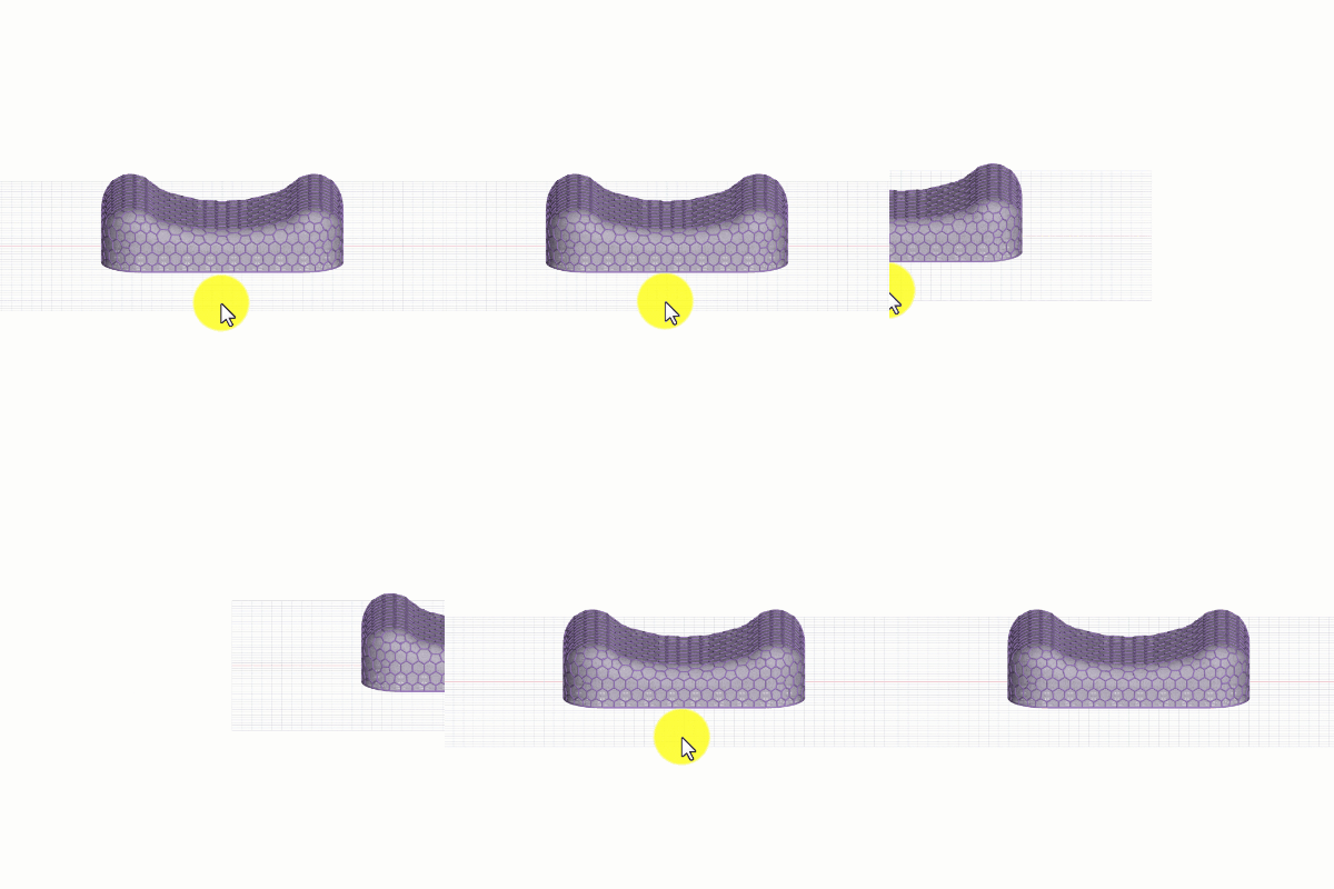
Pan
Move in two dimensions
Usage
- Mouse/Touchpad and Keyboard - Press Shift + right-click and drag
- Mouse - Press middle mouse button and drag
Orbit
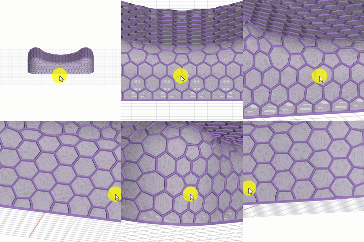
Move in three dimensions around the world origin (Default behavior)
Usage
- Mouse and Touchpad - Right-click and drag
Views
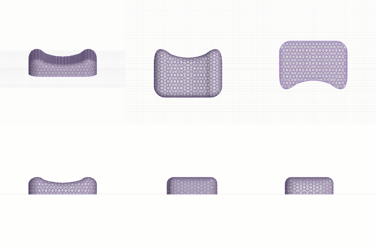
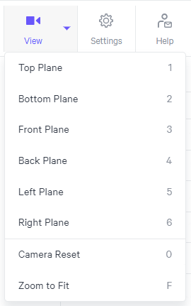
Planar Views
Snaps to orthogonal views: Top, bottom, front, back, left, right
Usage
- Keyboard shortcut 1-6
- Rotate camera 45° ← ↑ → ↓
- Rotate camera 90° shift ← ↑ → ↓
- View Menu
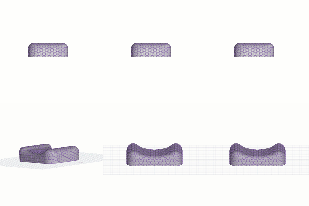
Camera Reset
Zooms to a preset central view
Usage
- Keyboard shortcut 0
- View Menu
Keyboard Shortcuts
A handful of keyboard shortcuts are available in Carbon Design Engine.
Feature | Shortcut |
|---|---|
Measure | M |
Hide/Show grid | B |
Toggle clip plane | C |
Change slider by 1 | < or > |
Change slider by 10 | shift-< or > |
Undo | Ctrl/cmd-Z |
Redo | Ctrl/cmd-shift-Z |
Strut Lattice Diameter View | Ctrl/cmd-M |
Planar Views Top | Bottom | Front | Back | Left | Right | 1 | 2 | 3 | 4 | 5 | 6 |
Rotate camera 45° | ← ↑ → ↓ |
Rotate camera 90° | shift ← ↑ → ↓ |
Camera Reset | 0 |
Zoom to Fit | F |
Zoom toward Cursor | - |
Disable snap in Edit Strut - Add Strut mode | Hold shift |
File Options
Visibility Options
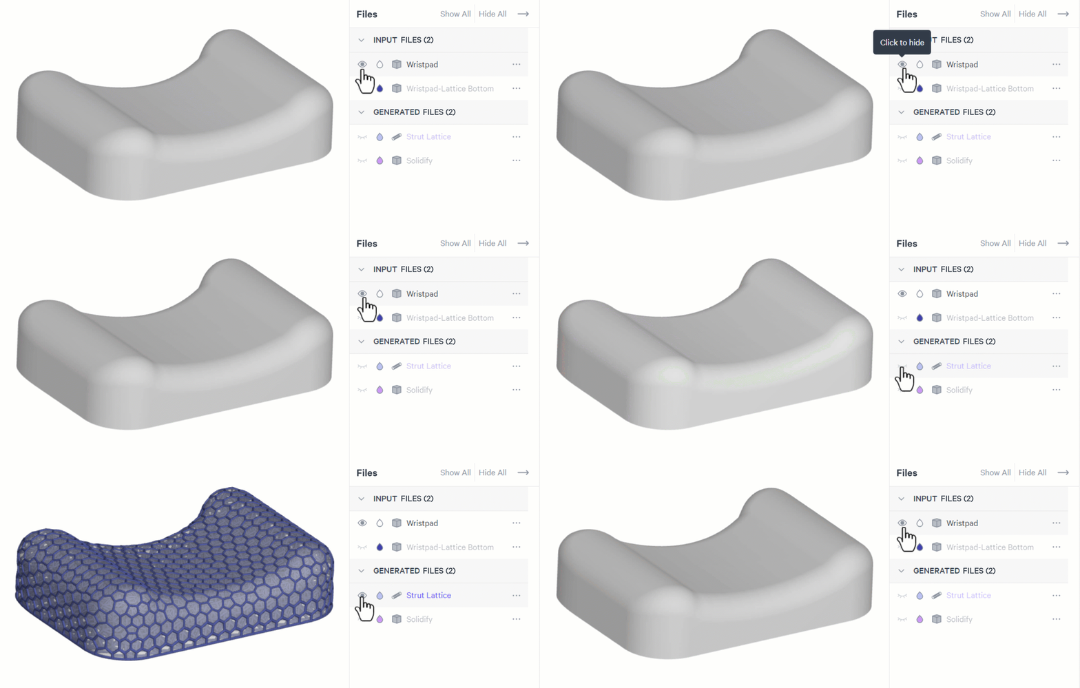
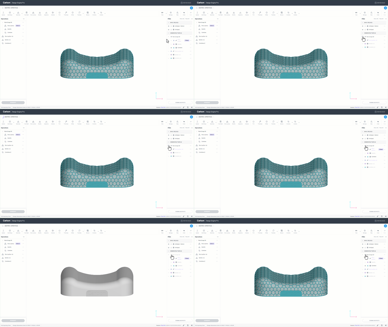
Show/Hide
- Click on the open eye 👁 icon to hide visible files
- Click on the closed eye ⏑ icon to show hidden files
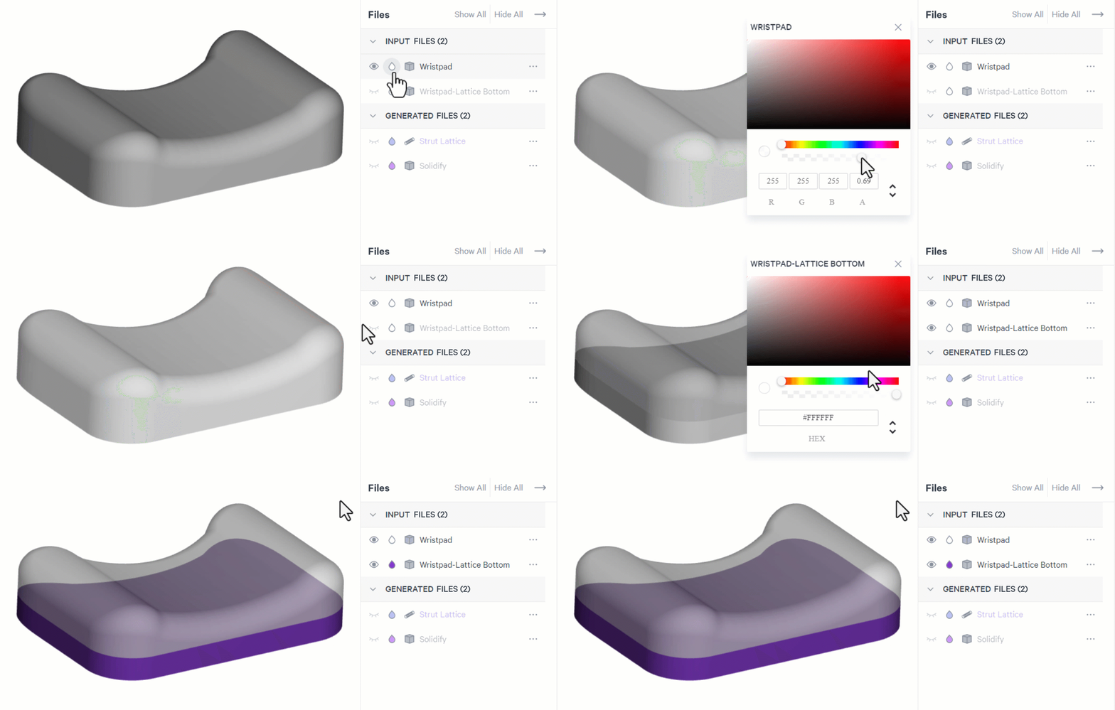
Appearance
- Adjust transparency with the slider bar | or enter a value in the alpha field (RGBA)
- Adjust color with the slider bar for hue and on the color field for tone | or enter a hex code
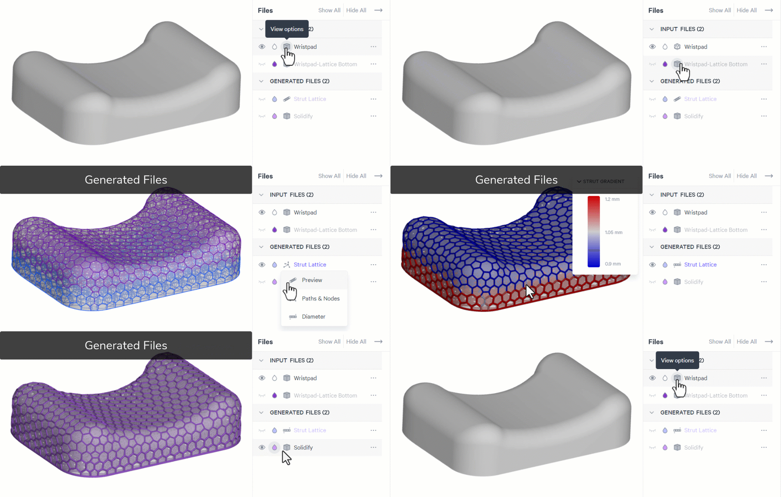
View Options
Input Files
- Select Shaded for a simple shaded view
- Select Triangle to view the STL triangles compiling the mesh
Generated Files
- Strut Lattice
- Select Preview for a volumetric preview of the struts
- Select Paths & Nodes for a line view of the struts
- Select Diameter to view a colored gradient representation of strut diameter. (Ctrl/cmd-M keyboard shortcut)
- Ranging from red (largest) to gray (middle) to blue (smallest).
- Hover over a strut to view its diameter, length, and whether it is a boundary strut
- Solidify
- Default View Only
File Menu Options
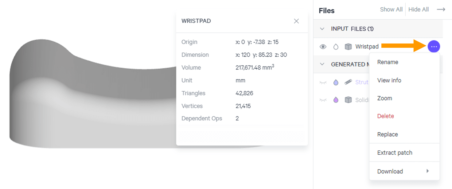
Various options are available from the files menu. Options will vary depending on the file type.
Potential Menu Options
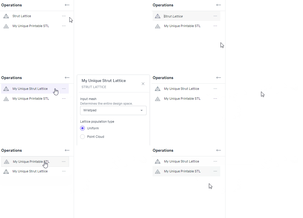
- Rename - Change the name of the file
- View info - View metrics that define the file(stats may vary depending on the selected file)
- Zoom - Zooms to the extents of the file and centers in the project area
- Delete - Removes the file from the project
- Replace - Update the input file with a revised file. This will update the file in all operations where selected. Patches will need to be reselected.
- Extract (or edit) Patch - Available for design spaces, this opens the Extract Patch interface to extract a surface for use in applicable tools & features
- Edit - Available for strut lattices to bring up the editing interface to delete, modify, and/or add struts
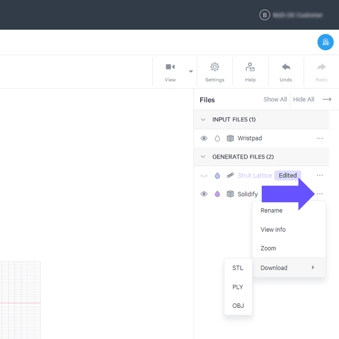
- Download - Download the STL file. Alternate file options available in some cases. Not available for strut lattices
Strut Information
Hover over a strut in a lattice to view key information about the strut (diameter, length, and whether it is designated as a boundary strut or feature edge).
Note that the tooltip is available for strut lattices only and not solidified lattices.
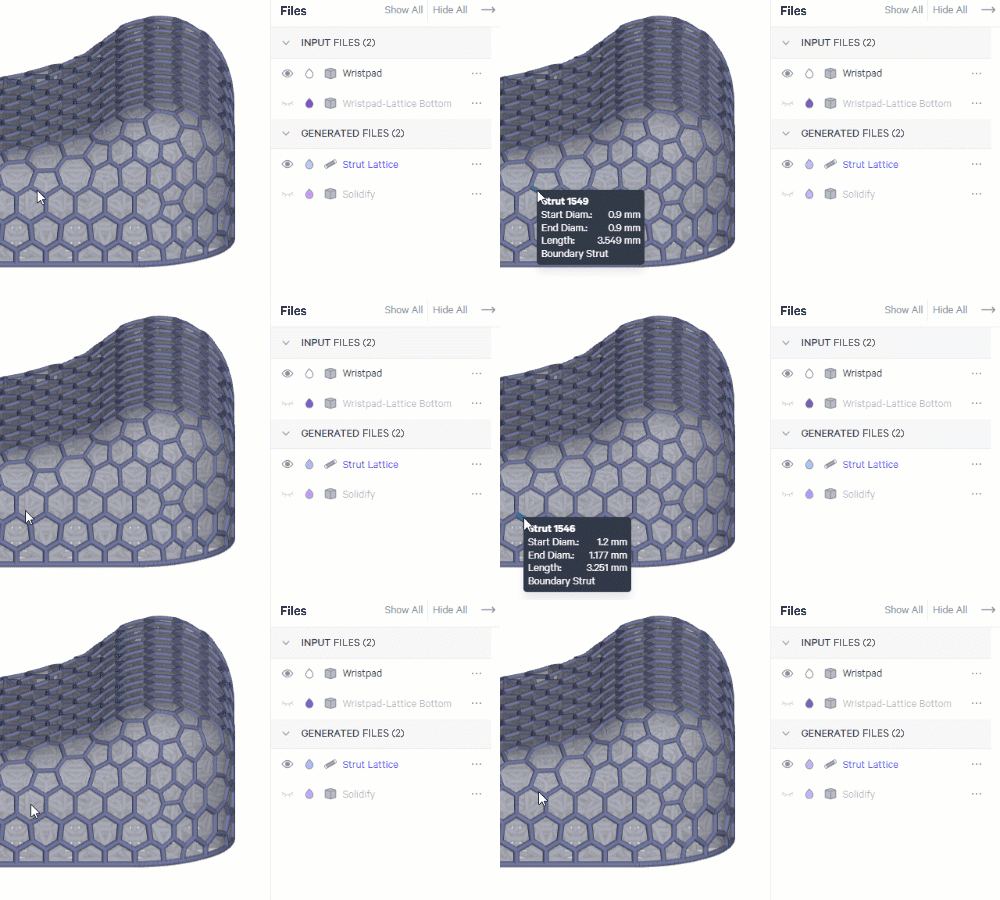
Detailed strut information can be useful when editing struts or reviewing the results of a zonal lattice structure that includes different strut parameters.
Replace File
When a file is used in multiple operations, you can update the file in all locations with the Replace function. This can be especially helpful if you are trying multiple iterations in one design.
Download Options
Design Engine provides multiple paths to downloading files. Alternate file options are available in some cases.
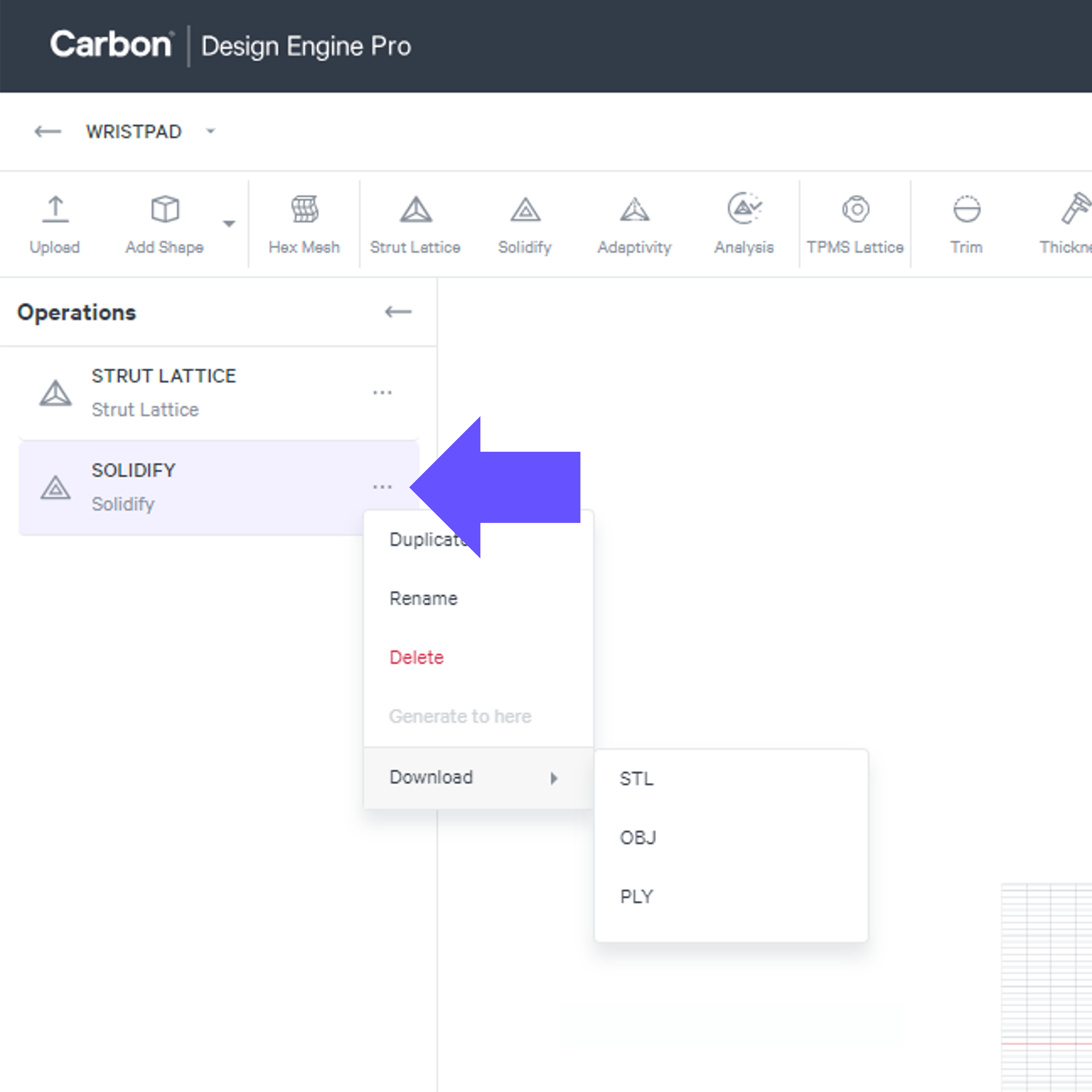
Operation List
The operation menu allows for downloading a single file.
When the file is an STL mesh, OBJ and PLY file types are also available for download.
Files List
The file menu allows for downloading a single file.
When the file is an STL mesh, OBJ and PLY file types are also available for download.
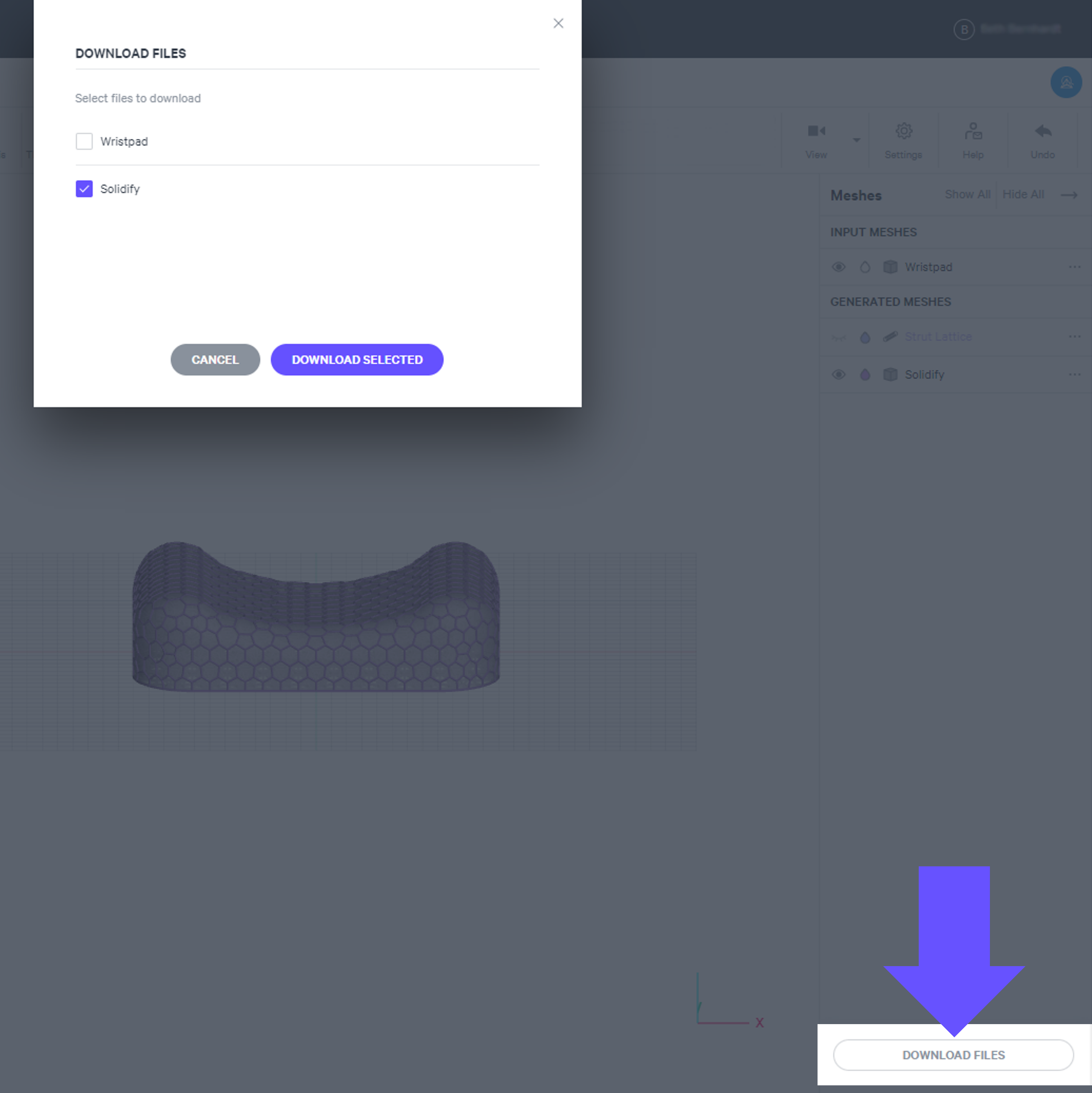
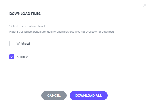
Download Files Button
The button allows for selecting multiple files to download at once.
File type is STL only.
Protected File States
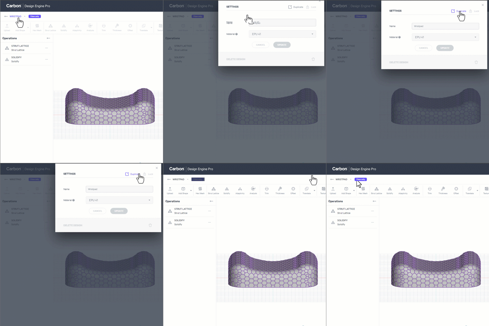
View Only
When you open a project created by another user, the project will open as View Only to prevent unwanted edits. A new user can duplicate the project to edit a new version.
Locked
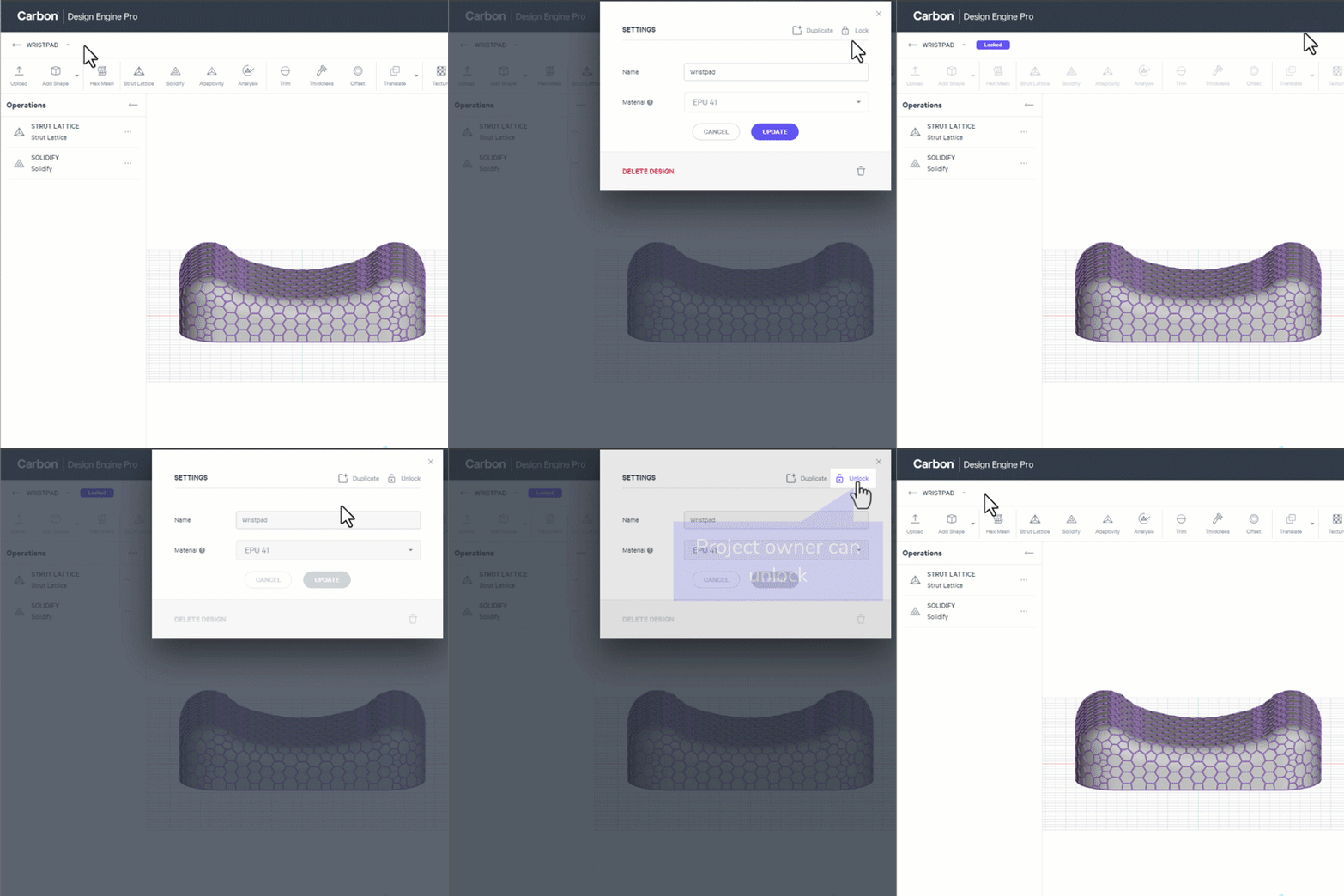
A project owner can create a Locked state.
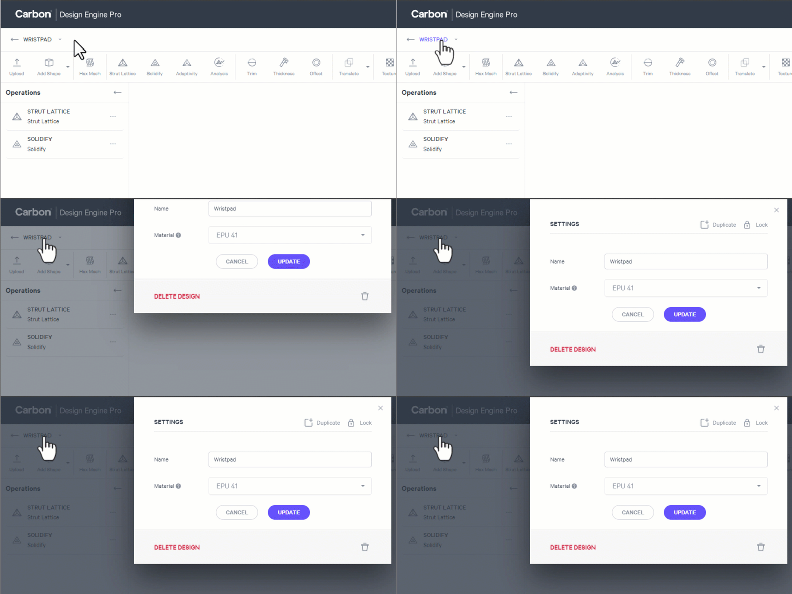
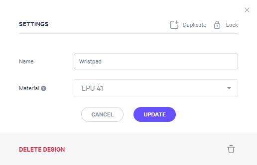
- Click design name to launch settings
- Lock project to prevent changes
- Options with a locked project:
- Duplicate file to work on a new version
- Project owner can unlock
Operations Options
Grouping Operations
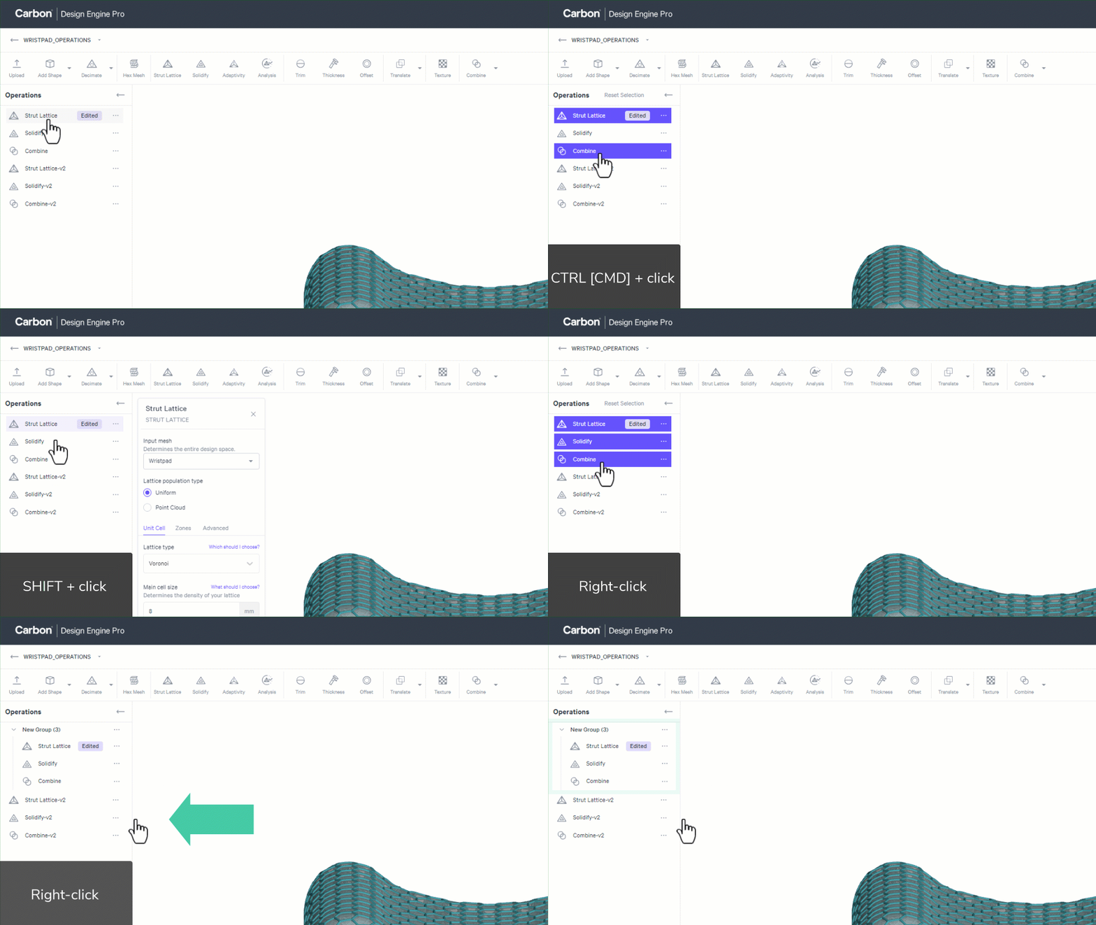
Operations can be grouped, allowing for easier management of large, complex design projects.
Create an Operation Group
- Select multiple operations
- Individually with CTRL+click [Windows] or CMD+click [Mac]
- As a series with SHIFT+click
- Right-click and select Create new group
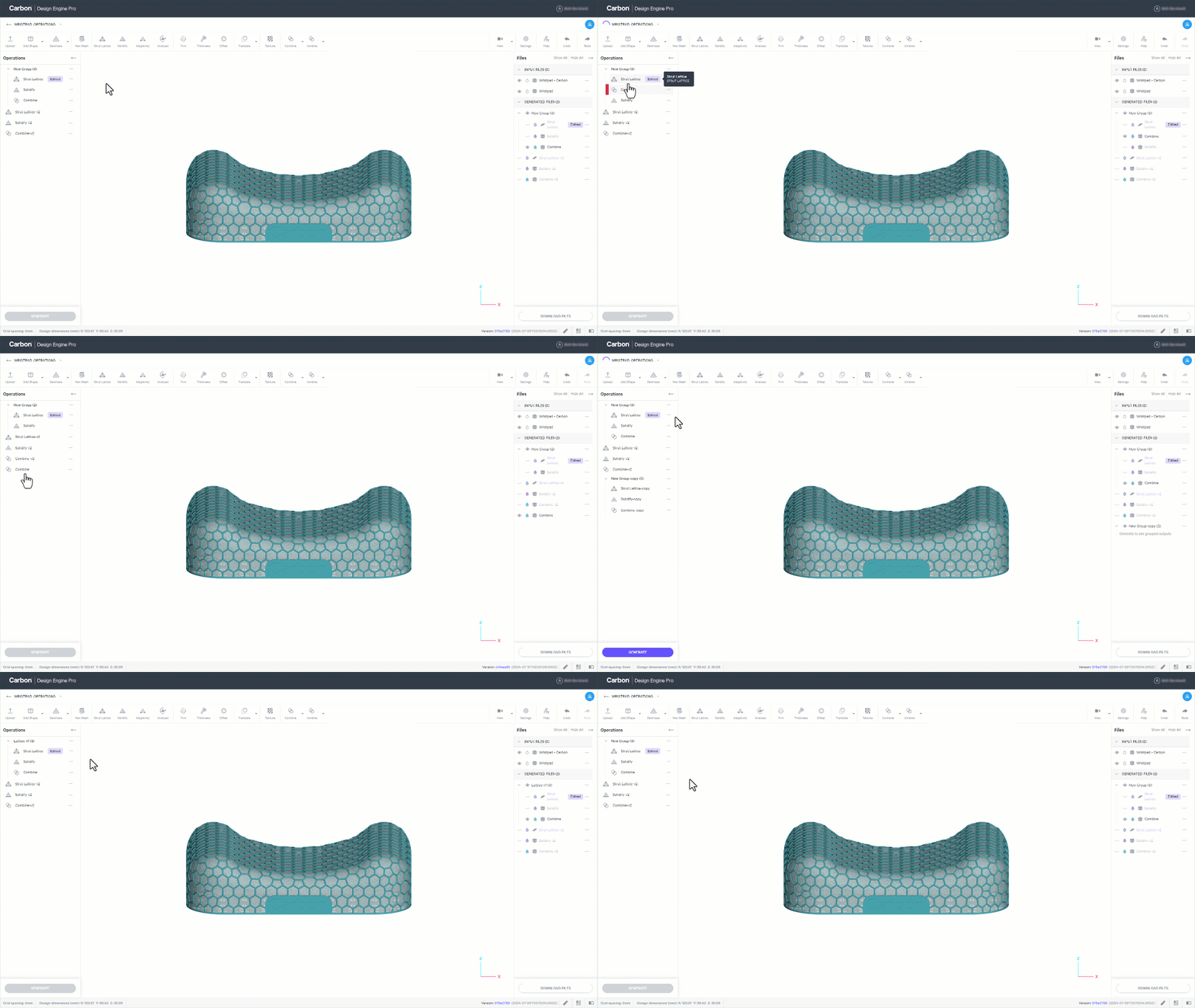
Once an Operation Group is created, the following actions can be taken
- Expand or collapse visibility of the grouped operations
- Re-order the operations with in the group
- Re-order the group's position in the operations list
- Move individual operations into and out of the group
- Click and drag or
- Use the operation menu (right-click or ... ) to Add to existing group/Remove from group
- Duplicate the group
- Rename the group
- Ungroup the operations
- Delete the group (including all operations within)
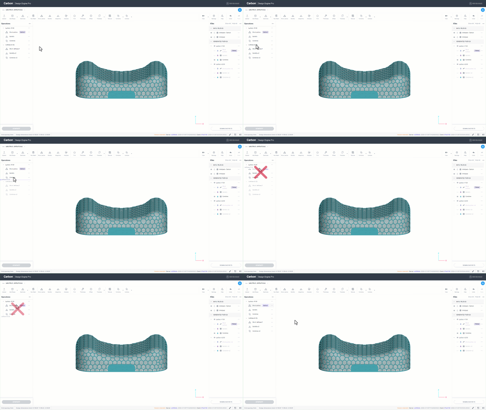
Generate to Here
When you change a variable in an operation that requires re-generating the design, you have the option to generate only up to a particular operation to save the processing time of subsequent operations.
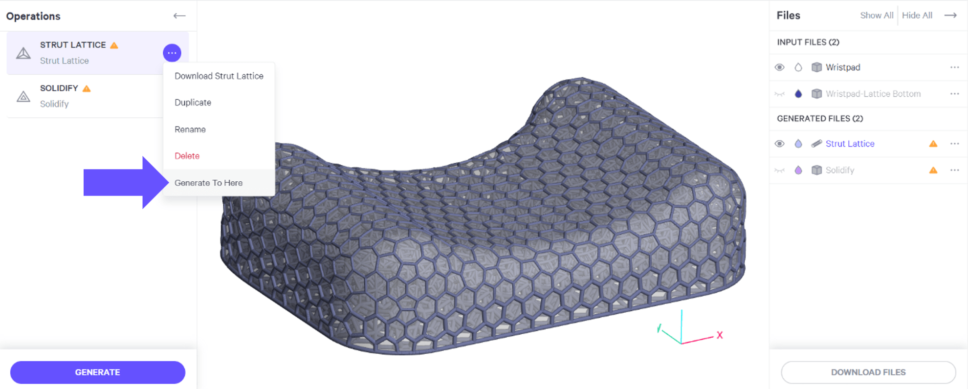
This is similar to a rollback bar in CAD programs.
- Select the menu of the operation you wish to generate up to.
- Select Generate To Here
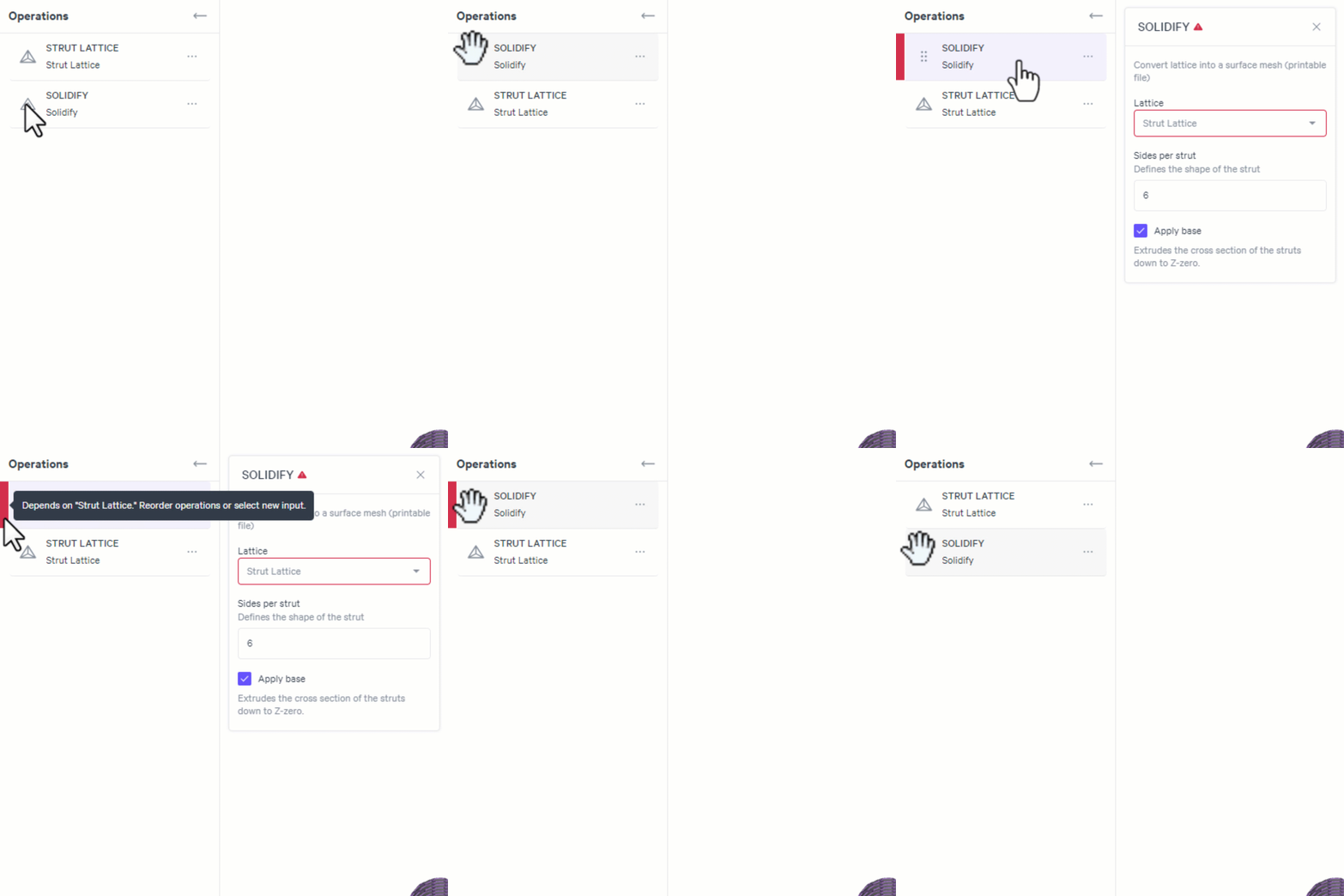
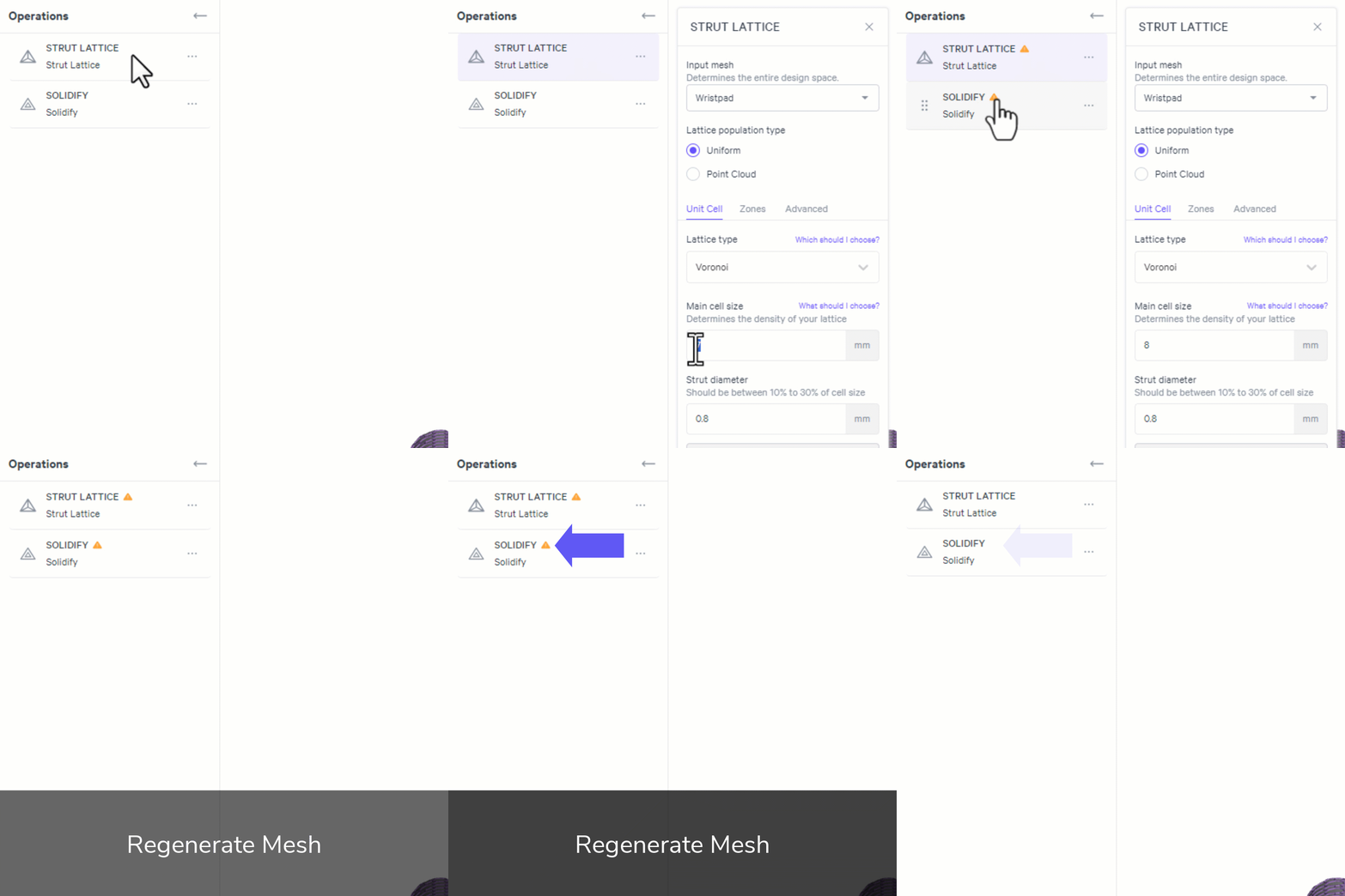
Operation Dependencies
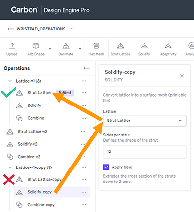
Adjusting operations may affect dependencies, ie operations that reference each other.
Error Errors are marked in red when an operation will fail to generate due to a dependency.
Hovering on the red explains the error. In this case: Depends on "Strut Lattice." Reorder operations or select new input.
Warning Warnings are marked in orange to alert you that something has been adjusted requiring a regeneration.
Hovering on the orange explains the warning. In this case: Output is stale. Operation inputs or values have changed.