---
title: Orientation and Supports
slug: process/orientation-and-supports
description: Explore the essential strategies for optimizing part orientation and supports in Carbon DLS production. Learn how to balance critical factors to ensure print success, support your design needs, and balance cost.
docTags:
createdAt: 2024-06-28T18:32:06.449Z
---
Orienting and supporting parts is a challenging process with multiple considerations at play. There may be more than one solution for a successful print. Determining the best option for any given geometry is a process of balancing priorities with the dynamics of the printer.
### Orientation
::::VerticalSplit{layout="left"}
:::VerticalSplitItem
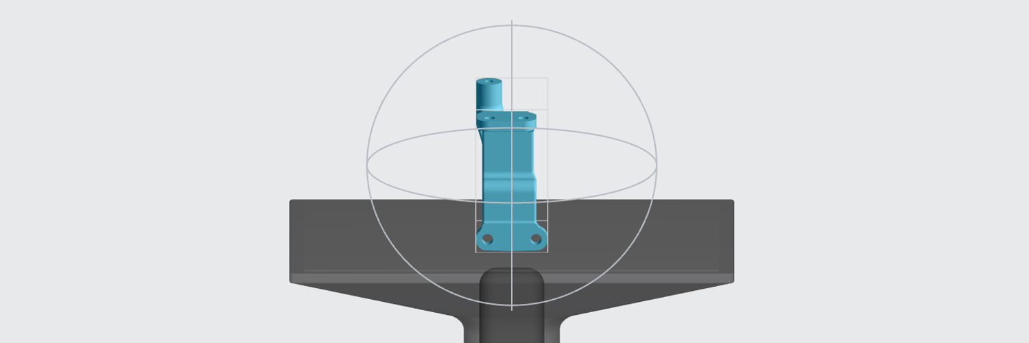
Orientation is the position a part sits in XYZ relative to the platform and print direction.
:::
:::VerticalSplitItem
:::
::::
### Supports
Supports are a temporary structure, printed in the same material as the part, that may be required to ensure successful printing. Supports are removed after printing. Conditions that require supports are:
::::VerticalSplit{layout="right"}
:::VerticalSplitItem
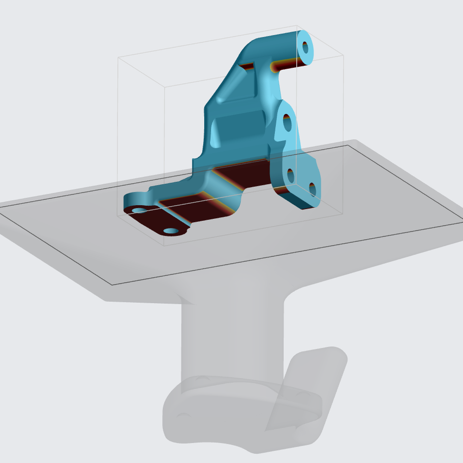
**Overhangs** (and Bridges)
Any feature that projects from the part either horizontally (parallel to the platform) or below the recommended self-supporting angle. (Shown in red)
Reference [recommended features sizes](docId\:t94PR-A-C0pIhY6LJsWk7) for overhang distance and self-supporting angles per resin.
:::
:::VerticalSplitItem
:::
::::
::::VerticalSplit{layout="right"}
:::VerticalSplitItem
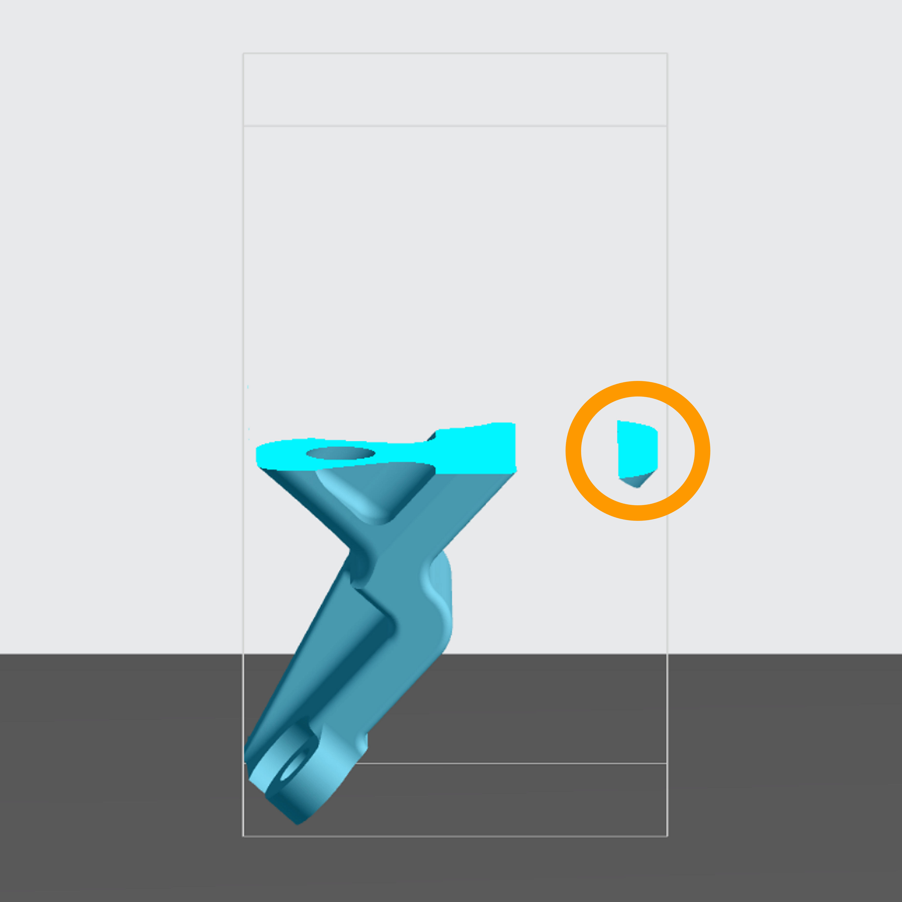
**Island**
A feature that begins printing above the platform before it is connected to the rest of the part.
:::
:::VerticalSplitItem
:::
::::
::::VerticalSplit{layout="right"}
:::VerticalSplitItem
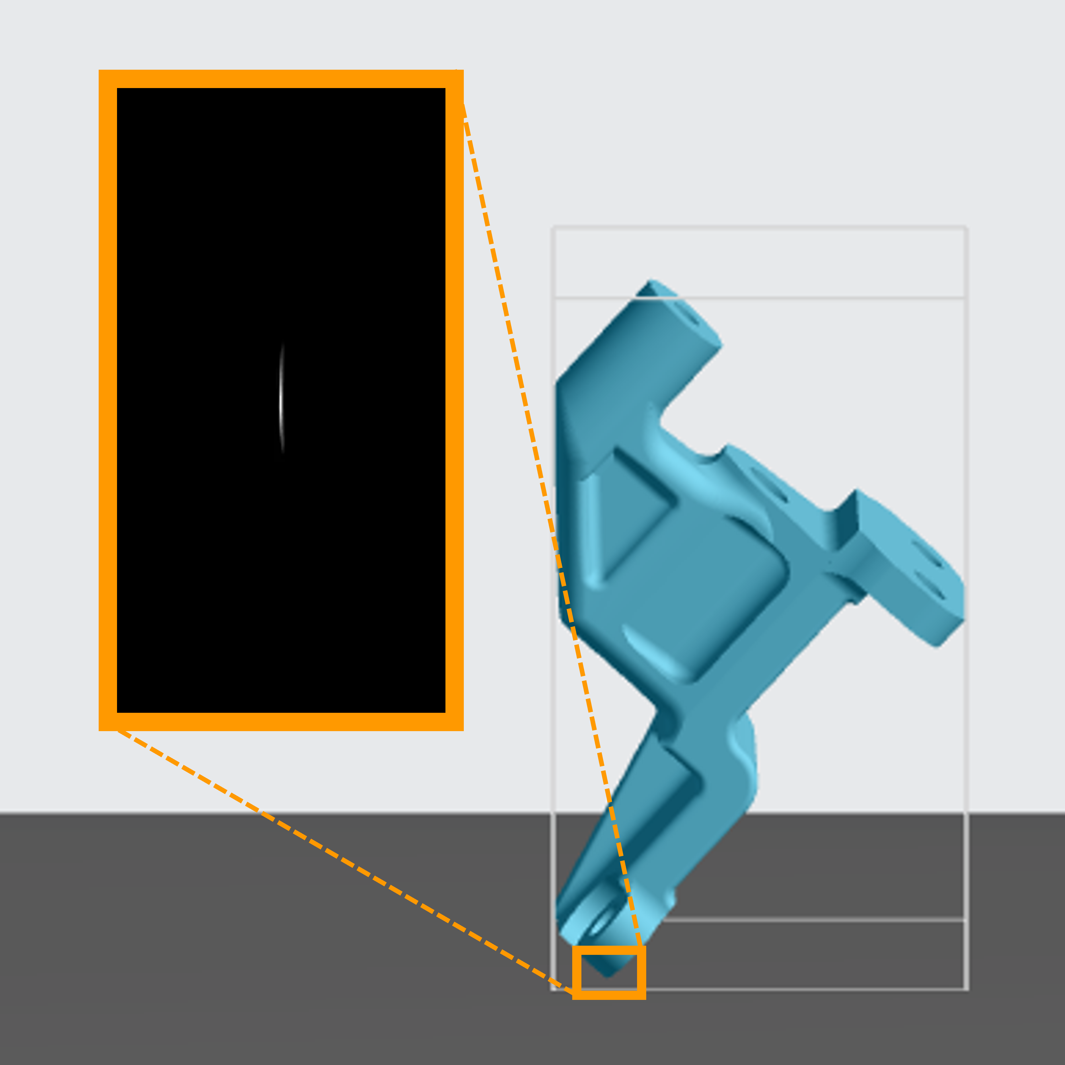
**Adhesion**
When a part or its orientation does not have enough surface contact with the platform to hold on at the start of a print, adhesion supports or a different orientation are needed.
Reference [DLS Printer Dynamics](docId\:U7XYytjyDp3BvsYy2qKcU).
:::
:::VerticalSplitItem
:::
::::
::::VerticalSplit{layout="right"}
:::VerticalSplitItem
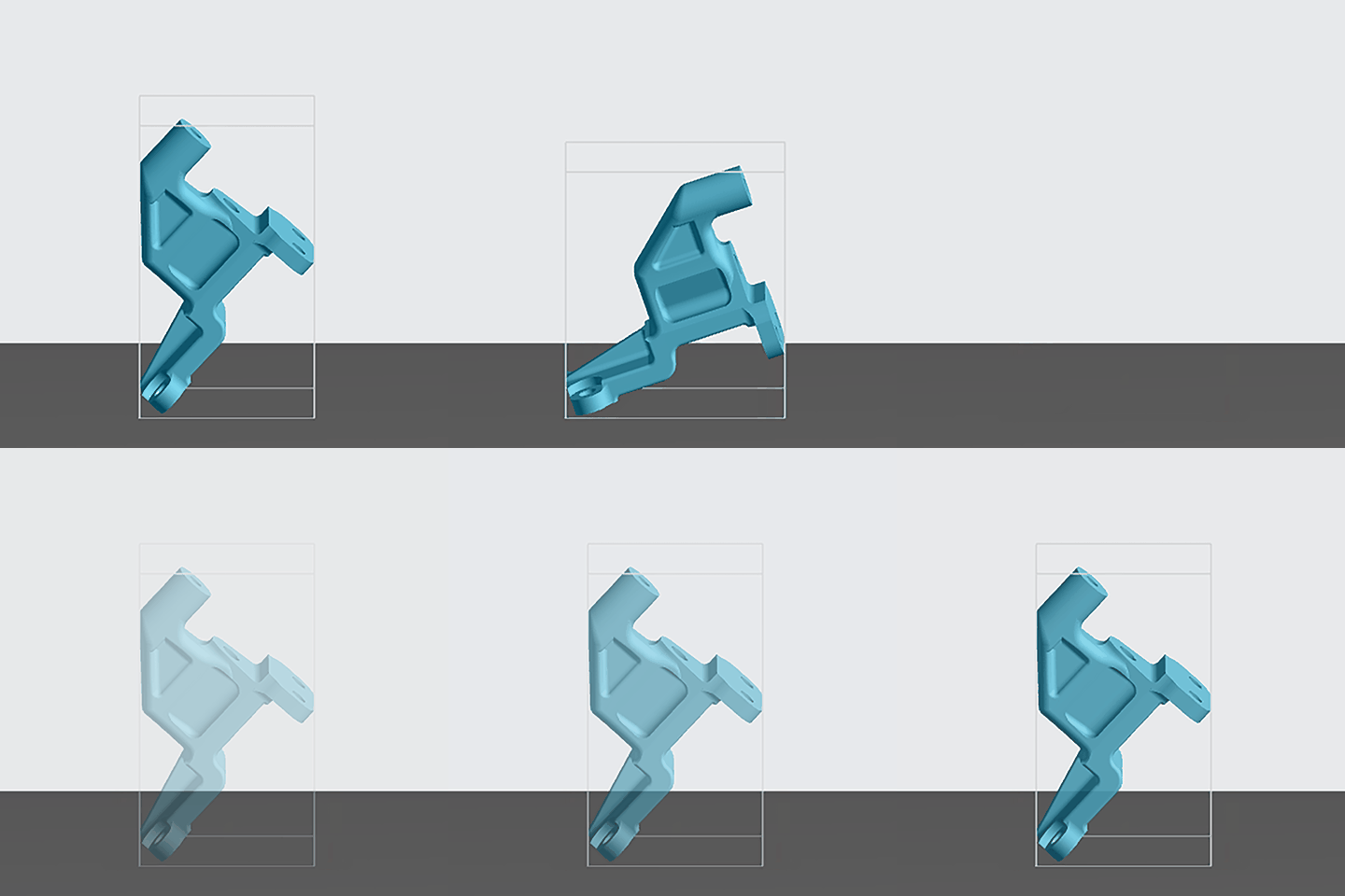
**Stability**
Supports are needed to allow the part to withstand the suction forces of printing.
Reference [DLS Printer Dynamics](docId\:U7XYytjyDp3BvsYy2qKcU).
:::
:::VerticalSplitItem
:::
::::
:::hint{type="info"}
This guide walks through **strategy** for making orientation and supports decisions.
For documentation on what tools you have available inside the Printer UI and how to use them, refer to the [Orient](docId\:rMnxtq1NIAHXZOc4bZXWu) and [Supports](docId\:VUbpoAitbLM11aM9-qJ1p) pages.
:::
### Assessment Criteria
The choices you make orienting and supporting your parts will have an effect on the printed outcome. Assess your choices against the following criteria:
- [Print Success](docId\:DoBa4qKKoXpi-52yw3nCr)
- Dynamics of the printer can affect print success across differing orientations and supports solutions.
- Utilize Auto Orientation as the best starting place for print success.
- [Design](docId\:DoBa4qKKoXpi-52yw3nCr)
- Outline what features are the most critical.
- Note the most important cosmetic surfaces.
- [Cost](docId\:DoBa4qKKoXpi-52yw3nCr)
- Printing time, resin usage and labor are all affected by orientation and supports.
- Compare cost among orientation and supports options.
:::hint{type="info"}
Example assessment exercises are provided on the following pages in this guide:
[Orientation Assessment](docId:2Yr4OFt_Lo0mOHUcloiQo)
[Supports Assessment](docId\:tbJP6hrVG-t5Dst6NMyzB)
:::
# Print Success
## Unsupported Features
Features that may not print properly if left unsupported:
- Overhangs/bridges over the [recommended feature size](docId\:t94PR-A-C0pIhY6LJsWk7)
- Islands
[Project Analysis](docId\:gfR-GoC-Irq_L9_KanC-X) warns you of any islands in your project.
***Example Corner Cube Part***
:::::::WorkflowBlock
::::::WorkflowBlockItem
**Overhangs**
::::VerticalSplit{layout="right"}
:::VerticalSplitItem

:::
:::VerticalSplitItem
On the dark gray background, you can see how the part is sitting on the platform.
Viewed from below in the main image, the **overhang detection tool** highlights overhangs/bridges in **red**.
*The dark gray surface is sitting on the platform.*
:::
::::
:::::ExpandableHeading
**Suggested Solution**
::::VerticalSplit{layout="right"}
:::VerticalSplitItem
- Measuring the smallest overhang/bridge confirms that all of the **larger red areas require supports**.
- *Distance falls over the recommended minimum, 2mm for most resins.*
:::
:::VerticalSplitItem

:::
::::
::::VerticalSplit{layout="right"}
:::VerticalSplitItem
- The largest flat red area receives **bar supports**.
- The thinner red areas receive **fence supports**.
:::
:::VerticalSplitItem
::Image[]{src="https://api.archbee.com/api/optimize/vMzsbEjDegHbwm-J2w3HR-KfSbfg5O-Q5QrrOuwoXz3-20240830-223344.gif" size="98" width="575" height="575" position="center" alt="Adding supports" showCaption="false"}
:::
::::
::::VerticalSplit{layout="right"}
:::VerticalSplitItem
- Remaining red areas are too small to need supports.
:::
:::VerticalSplitItem

:::
::::
:::::
::::::
:::::WorkflowBlockItem
**Islands**
::::VerticalSplit{layout="right"}
:::VerticalSplitItem

:::
:::VerticalSplitItem
**Two islands** emerge partway through the print that require supports.
:::
::::
:::ExpandableHeading
**Suggested Solution**
Reorienting parts can be an effective method to **minimize overhang/bridges and islands**, thereby reducing the supports needed to achieve print success.
**Utilize self-supporting angles** to reduce overhangs.
Reference [recommended angle](docId\:t94PR-A-C0pIhY6LJsWk7) per resin. 40 degrees or more from horizontal is most common.

:::
:::::
:::::::
## Cross Section
Cross section is the XY slice of the part being printed at a given point in time, which can be seen when you [view slices](docId\:gfR-GoC-Irq_L9_KanC-X) for the project.
***Goals***
- **Small** cross sections
*(less than 50 x 50 mm recommended)*
- **Consistent** cross sections throughout the print
- **Gradual** changes in cross section from slice to slice
***Risks***
:::::::WorkflowBlock
::::::WorkflowBlockItem
[Over-Adhesion](docId:6k62sHy9n_S4Srwm6PAZc)
Parts with a large cross section on the platform will have strong adhesion and may be more difficult to remove from the platform. For especially rigid and brittle resins (ex: EPX), this can result in chipping the part during removal.
::::VerticalSplit{layout="middle"}
:::VerticalSplitItem

:::
:::VerticalSplitItem

:::
::::
:::::ExpandableHeading
**Suggested Solution**
Lift part up on supports
- This example part does not want supports on any of the blade features, so reorientation would not work
- The support nubs on the bottom can easily be sanded off
- Lifting on supports also provides venting for the central hole
::::VerticalSplit{layout="middle"}
:::VerticalSplitItem

:::
:::VerticalSplitItem

:::
::::
:::::
::::::
::::::WorkflowBlockItem
[Under-Adhesion](docId\:DAbqNXb4KnG1eeiClRzqF)
Parts with a large cross section late in the print, in conjunction with a small cross section on the platform, can be susceptible to an adhesion failure due to suction forces.
::::VerticalSplit{layout="right"}
:::VerticalSplitItem
- Small cross section on platform
- Large cross section late in print
:::
:::VerticalSplitItem

:::
::::
::::VerticalSplit{layout="right"}
:::VerticalSplitItem
- Slices during printing
:::
:::VerticalSplitItem

:::
::::
::::VerticalSplit{layout="right"}
:::VerticalSplitItem
- Adhesion Failure from Suction Forces
:::
:::VerticalSplitItem

:::
::::
:::::ExpandableHeading
**Suggested Solution**
Reorient part for consistent cross sections throughout print.
::::VerticalSplit{layout="middle"}
:::VerticalSplitItem

:::
:::VerticalSplitItem

:::
::::
:::::
::::::
::::::WorkflowBlockItem
[Cross Section Line](docId:7TYKEfAqK6hnwMvjVW6Xj)
Abrupt changes in cross section, especially when a bridge suddenly closes, results in a geometry flow band: a line in the printed part when the cross section changes suddenly.
::::VerticalSplit{layout="right"}
:::VerticalSplitItem
- Slice just before an abrupt cross section change
:::
:::VerticalSplitItem

:::
::::
::::VerticalSplit{layout="right"}
:::VerticalSplitItem
- Abrupt cross section change
:::
:::VerticalSplitItem

:::
::::
::::VerticalSplit{layout="right"}
:::VerticalSplitItem
- Resulting cross section line
:::
:::VerticalSplitItem

:::
::::
:::::ExpandableHeading
**Suggested Solution**
Reorient part for gradual cross section changes.
**POOR**** Overall Cross Sections**
::::VerticalSplit{layout="middle"}
:::VerticalSplitItem

:::
:::VerticalSplitItem

:::
::::
**GOOD**** Overall Cross Sections**
*Result of auto orientation*
::::VerticalSplit{layout="middle"}
:::VerticalSplitItem

:::
:::VerticalSplitItem

:::
::::
:::::
::::::
:::::::
## Resin Flow
Prints are most successful when the resin can flow freely and consistently.
***Risks***
:::::::WorkflowBlock
:::WorkflowBlockItem
[Cross Section Line](docId:7TYKEfAqK6hnwMvjVW6Xj)
As with cross section described above, abrupt changes from one slice to the next cause a change in resin flow which results in a cross section line: a line in the printed part when the cross section changes suddenly. (see example above)
:::
::::::WorkflowBlockItem
[Witness Line](docId:4rLeAwnEPIMBuA6A1pcrm)
::::VerticalSplit{layout="middle"}
:::VerticalSplitItem
Resin flow can also cause a shallow line to appear on your part when the speed and direction of resin flow changes during printing. This can happen with parts of varying height on one build or when the platform moves above the resin surface. This is most common with elastomeric materials.
:::
:::VerticalSplitItem

:::
::::
:::::ExpandableHeading
**Suggested Solution**
::::VerticalSplit{layout="middle"}
:::VerticalSplitItem
Reorient the part by tilting it to break the resin's surface tension gradually rather than disrupt the flow across many areas at once.
:::
:::VerticalSplitItem

:::
::::
:::::
::::::
:::::WorkflowBlockItem
[Resin Starvation](docId:3EIqqQqCGKwU6QNgdR5Ox)
If resin is trapped in the part during printing, you could end up with an inadequate amount of liquid resin in the cassette to finish the print (when the minimum amount of required resin is in the cassette).
::::VerticalSplit{layout="middle"}
:::VerticalSplitItem

:::
:::VerticalSplitItem
This is most common with unvented volumes.
The example here, printed directly on the platform, trapped resin in the six holes and didn't have enough liquid resin left in the cassette to properly flow where needed to finish the print.
See [Unvented Volumes](docId\:DoBa4qKKoXpi-52yw3nCr) below for more information.
:::
::::
:::::
:::::::
## Unvented Volumes
::::VerticalSplit{layout="middle"}
:::VerticalSplitItem
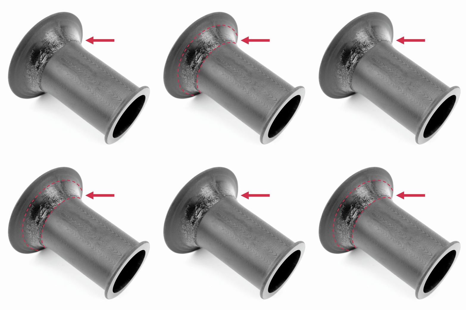
Unvented volumes trap resin in a pressure vacuum during printing which can cause print defects.
:::
:::VerticalSplitItem

:::
::::
**Possible defects** from an unvented volume:
::::LinkArray
:::LinkArrayItem{headerType="IMAGE" headerImage="https://api.archbee.com/api/optimize/dptYqcTHPbVZhe3zuNg4v-4mgbgODEtgs7k2eJ_EcBV-20250102-002645.png"}
[Blow Out](docId\:ygAbVQOmuTwYuvDOvnBfN)
:::
:::LinkArrayItem{headerType="IMAGE" headerImage="https://api.archbee.com/api/optimize/dptYqcTHPbVZhe3zuNg4v-7GbQP6v8GfPdZx2ZzfMyu-20250225-022037.gif"}
[Fringing](docId\:UP-Tsq77rAZxLvuEVCVmq)
:::
:::LinkArrayItem{headerType="IMAGE" headerImage="https://api.archbee.com/api/optimize/dptYqcTHPbVZhe3zuNg4v-t0GDLIR-_HTH_V4u4TV4e-20250102-010136.png"}
[Vacuum Line](docId\:uIA3VrtjsNOqvyXwL8VxS)
:::
::::
Related defects that unvented volumes can exacerbate:
::::LinkArray
:::LinkArrayItem{headerType="IMAGE" headerImage="https://api.archbee.com/api/optimize/dptYqcTHPbVZhe3zuNg4v-CZDwh_lptvzK6jz9vmlTm-20250102-004959.png"}
[Resin Starvation](docId:3EIqqQqCGKwU6QNgdR5Ox)
(by trapping resin)
:::
:::LinkArrayItem{headerType="IMAGE" headerImage="https://api.archbee.com/api/optimize/dptYqcTHPbVZhe3zuNg4v-xCXwS20-vkvjurjQUk7EB-20250222-013933.png"}
[Under-Adhesion](docId\:DAbqNXb4KnG1eeiClRzqF)
(from suction forces)
:::
::::
:::::::WorkflowBlock
::::::WorkflowBlockItem
[Fringing](docId\:UP-Tsq77rAZxLvuEVCVmq)
::::VerticalSplit{layout="middle"}
:::VerticalSplitItem
This example shows the fringing defect, but the same solutions can apply to all defects caused by an unvented volume.
:::
:::VerticalSplitItem
:::
::::
::::VerticalSplit{layout="middle"}
:::VerticalSplitItem
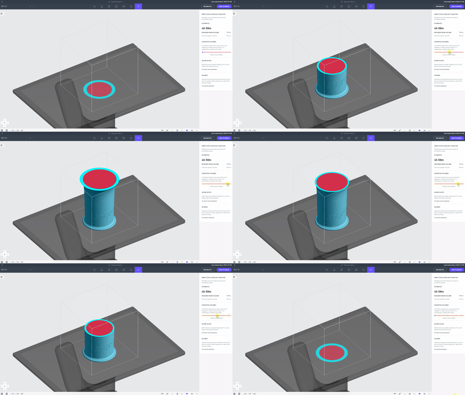
[Project Analysis](docId\:gfR-GoC-Irq_L9_KanC-X) in the Printer UI will look for unvented volumes in your part(s) and provide a warning for areas of trapped volume.
You can view the **warning areas in red** with a sliding scale that simulates the part through printing.
:::
:::VerticalSplitItem
:::
::::
:::::ExpandableHeading
**Suggested Solutions**
**Lift Part onto Supports**
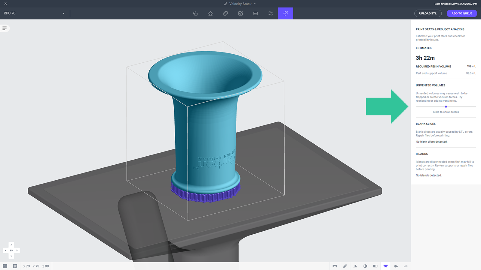
For this part, lifting the part onto supports provides venting among the supports. The Project Analysis now shows **no warnings** of trapped volumes.
***
**Reorienting a Part** may also eliminate the unvented volume.
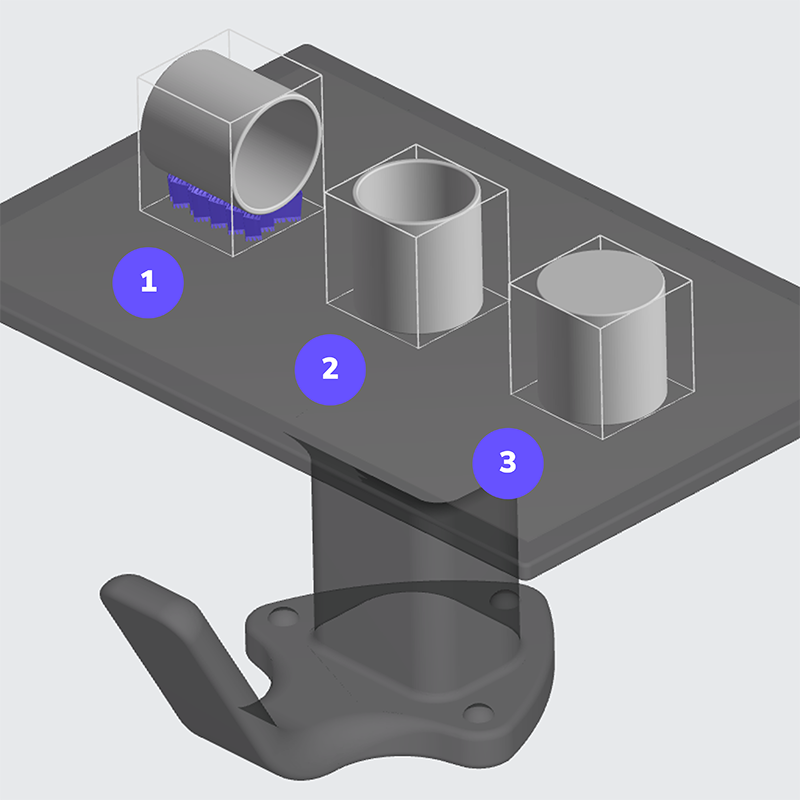
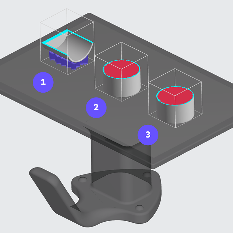
**Quiz: Which of the three orientations below has an unvented volume?**
::::VerticalSplit{layout="middle"}
:::VerticalSplitItem
**Answer**
Options **2 and 3** have unvented volumes, shown in red.
**Are you curious why option 2 is unvented even though it is open at the top?**
Option 2 will release the trapped volume when the print is finished and the platform returns home, but during printing, that opening is below the surface of the resin, thereby leaving that volume trapped under the same pressure as option 3.
:::
:::VerticalSplitItem
:::
::::
:::::
::::::
:::::::
## Stability
Stability is needed to counter the [suction forces](docId\:U7XYytjyDp3BvsYy2qKcU) of printing.
:::::::WorkflowBlock
::::::WorkflowBlockItem
[Under-Adhesion](docId\:DAbqNXb4KnG1eeiClRzqF)
::::VerticalSplit{layout="middle"}
:::VerticalSplitItem

:::
:::VerticalSplitItem
Parts susceptible to stability issues are top heavy or asymmetrical in their orientation, with a relatively small footprint on the platform. The resulting print defect is usually under-adhesion.
:::
::::
:::::ExpandableHeading
**Suggested Solutions**
**Supports**
When parts are unstable, supports add stability. This example is both tall and asymmetrical, making it susceptible to suction forces. The overhang detection tool has been turned on in the Printer UI, showing the underside of this part as yellow. ** Yellow indicates that this is a self-supporting angle, but stability supports may be needed.**
::::VerticalSplit{layout="middle"}
:::VerticalSplitItem

:::
:::VerticalSplitItem

:::
::::
::::VerticalSplit{layout="middle"}
:::VerticalSplitItem

:::
:::VerticalSplitItem
[Type of Supports](docId\:VUbpoAitbLM11aM9-qJ1p)
When stability is needed, it is better to use either bar supports or thickened fence supports.
- Bar supports are thicker and automatically truss together in the software to provide structure.
- Fence supports are thinner and can buckle when too tall. Edit the wall thickness to the [recommended wall thickness](docId\:t94PR-A-C0pIhY6LJsWk7) for the resin.
:::
::::
***
**Orientation**
Reorienting a part can often help stability by** lowering the height: footprint ratio**.
This part's center of mass is far from the platform and requires supports for both stability and overhangs. Reorientation eliminates the need for supports, provides a consistent cross section, and shortens the print time.
::::VerticalSplit{layout="middle"}
:::VerticalSplitItem

:::
:::VerticalSplitItem

:::
::::
:::::
::::::
:::::::
:::hint{type="warning"}
Suggested **solutions for print success in this lesson focus solely on how orientation and supports** can help. Additional options may be available for the print defects described here, **including but not limited to design solutions**. Reference the [Part Defects](docId\:pPm8gmeGCY_0fkFwgTCyj) documentation for full troubleshooting options.
:::
# Design
## Cosmetic Surfaces
Surface finish may be important on parts that have highly visible surfaces, such as name plates or the exterior of housings. Orientation & supports strategies can be utilized to achieve the best surface finish where needed.
::::::WorkflowBlock
:::::WorkflowBlockItem
### Supports Location
Cosmetic surfaces can be oriented to avoid the need for supports.
::::VerticalSplit{layout="middle"}
:::VerticalSplitItem
**On Cosmetic Surface**

:::
:::VerticalSplitItem
**Off Cosmetic Surface**

:::
::::
:::::
:::::WorkflowBlockItem
### Medial Axis Flow Lines
::::VerticalSplit{layout="middle"}
:::VerticalSplitItem
Large cross sections parallel to the platform, facing the window, will manifest resin flow lines as a result of fluid dynamics.
Reorient cosmetic surfaces out of the ending XY plane to mitigate the effect.
:::
:::VerticalSplitItem

:::
::::
:::::
:::::WorkflowBlockItem
### Pixel Lines
::::VerticalSplit{layout="middle"}
:::VerticalSplitItem
Vertical surfaces can show vertical lines manifested from the corners of pixels in the slice image.
Reorient cosmetic surfaces out of the Z plane to mitigate the effect.
Reference [DLS Design Guidelines](docId\:t94PR-A-C0pIhY6LJsWk7) for more information on resolution.
:::
:::VerticalSplitItem

:::
::::
:::::
:::::WorkflowBlockItem
### Slice Lines
::::VerticalSplit{layout="middle"}
:::VerticalSplitItem
Shallow curved surfaces can show the edges of slices as the slice image's edges shift from one slice to the next.
Reorient cosmetic surfaces to minimize shallow curves to mitigate the effect.
Reducing the slice thickness can also reduce this effect but will increase the print time. Reference [Print Controls](docId\:N9rCrE4j391HMxwvP-udG).
Reference [DLS Design Guidelines](docId\:t94PR-A-C0pIhY6LJsWk7) for more information on resolution.
:::
:::VerticalSplitItem

:::
::::
:::::
:::::WorkflowBlockItem
### Consistency
::::VerticalSplit{layout="middle"}
:::VerticalSplitItem
Angled surfaces have the best consistency in surface finish as the combined effects of resin flow, pixels and slices average together.
It is particularly useful to match the print angle on multiple surfaces so they all share the same finish.
:::
:::VerticalSplitItem

:::
::::
:::::
::::::
## Fence vs Bar Supports
::::VerticalSplit{layout="middle"}
:::VerticalSplitItem

:::
:::VerticalSplitItem
**Fence Support Nubs are Smaller**
There are two types of supports.
1. **Bar supports**
The break line is farther from the surface of the part and therefore leaves behind a larger nub.
2. **Fence supports**
The break line is close to the surface of the part, leaving smaller, consistently spaces nubs.
:::
::::
## Critical Features
Your parts may have critical features where tolerance is tight and accuracy is important.
Orientation & supports decisions can be made to ensure the most critical features have the best outcome for your application.
::::::WorkflowBlock
:::::WorkflowBlockItem
[Optical Effects](docId\:t94PR-A-C0pIhY6LJsWk7)
**Overcure** and **cure-thru** are optical effects resulting from how UV light interacts with the resin as it's curing. Resin is not completely opaque to UV light, and some light passes through features edges where the material is thin, curing a small amount of additional resin.
1. **Overcure** occurs in the **XY** plane
2. **Cure-thru** occurs in the **Z** axis
Critical features maintain because overcure behaves equally across that plane. A vertically oriented feature will experience cure-thru only from the bottom (where the UV light shines from), causing a feature to be marginally oblong.
::::VerticalSplit{layout="middle"}
:::VerticalSplitItem

:::
:::VerticalSplitItem

:::
::::
:::hint{type="info"}
The overcure and cure-thru illustrated here have been exaggerated for graphic readability. The actual dimensional difference is smaller at scale. Reference [DLS Design Guidelines](docId\:t94PR-A-C0pIhY6LJsWk7) for more information on **optical effects** as well as recommended compensation factors for [holes.](docId\:t94PR-A-C0pIhY6LJsWk7)
:::
:::::
:::::WorkflowBlockItem
**Supports**
Features that serve a functional role may require special considerations to ensure proper fit in their application. Examples include:
- Holes that require a press fit or will serve specific hardware
- Surfaces that will be bonded to another component
- Snap fit features
**Orient Strategically for Function**
The function of this bracket requires a smooth interface on all flat faces to ensure a tight fit with construction components. Orienting the part such that supports are only on the edges of the part, the function of the bracket is improved.
::::VerticalSplit{layout="middle"}
:::VerticalSplitItem
**Functional assembly** of the bracket
:::
:::VerticalSplitItem
**Orientation with supports on a flat face****** **Orientation with all supports on edges**
:::
::::
::::VerticalSplit{layout="middle"}
:::VerticalSplitItem

:::
:::VerticalSplitItem

:::
::::
**Orient for No Supports on Features**
Orient your part to eliminate overhangs and the need for supports on critical features.

::::VerticalSplit{layout="middle"}
:::VerticalSplitItem
**Choose Fence Supports**
If the preferred orientation\* requires supports on critical features, choose fence supports to leave behind smaller support nubs.
*\*For example, this example orientation may be preferred for cosmetic reasons: to keep supports off of hero surfaces (see above).*
:::
:::VerticalSplitItem

:::
::::
:::::
::::::
## Assemblies
When parts will be assembled, it is recommended to orient each part consistently relative to how the components will fit together. Every axis, in each part, will then be exposed to printing forces in the same manner, leading to the best fit.

# Cost
## Material Cost - Supports
Supports are printed in the same material as the part. The more supports a part needs, the more cost is associated with the part. Utilize orientations that minimize the needs for supports to save on cost.
Reference the [Unsupported Features](docId\:DoBa4qKKoXpi-52yw3nCr) Print Success example for minimizing unsupported features.

## Print Time
Reducing print time is desirable to increase throughput. Orientation of the part can have a measurable impact on the print time.
:::hint{type="info"}
Note that ultimately what matters most for cost is the **print time per part**. The shortest print time is often at odds with the number of parts per build, so it makes sense to look at both factors in tandem and calculate the best **value per part**. Reference the [Tall vs Short Cost Comparison ](docId\:DoBa4qKKoXpi-52yw3nCr) below.
:::
**Part Height**
The most influential factor on print time is the height of the part. Drastically **reduced print times** can result from a **short orientation**.
:::hint{type="info"}
Note that print time rarely changes from one part to a fully packed build, unless parts are packed too closely. The examples below have the same print time for one part and for the full build.
:::
::::VerticalSplit{layout="middle"}
:::VerticalSplitItem

:::
:::VerticalSplitItem

:::
::::
*Estimates shown from an M3 Printer.*
*Other printers will vary due to build size, or on an M2 Printer (which has the same build volume as an M3) due to M3's force feedback feature that usually yields faster print times.*
## Parts per Build
Maximizing the number of parts per build is desirable to get as many parts through production as possible. Orientation of the part can have a great impact on how many parts fit on the build platform.
The [Minimize Footprint](docId\:rMnxtq1NIAHXZOc4bZXWu) tool in the Printer UI is the quickest way to get an orientation to maximize parts per build. This example yields 42parts per build with a minimal footprint, compared to 10 in a short orientation.
*Remember to follow part spacing recommendations: reference *[Layout](docId\:SJ39gtBagt0cSGVVlCfli).
::::VerticalSplit{layout="middle"}
:::VerticalSplitItem

:::
:::VerticalSplitItem

:::
::::
:::hint{type="info"}
**Tall vs Short Cost Comparison**
Note that while maximizing the build can often provide a good value, it is important to look at **all factors affecting cost** on a per part basis, notably those mentioned above: **material and print time per part**.
The example above fares better in the short orientation for print time per part and material cost per part (due to fewer supports). The deciding factor may come down to other factors. Reference the [Example Orientation Assessment](docId:2Yr4OFt_Lo0mOHUcloiQo) for full considerations at play.
:::
***
## Post-Processing
Orientation & Supports decisions can have a noticeable impact on the effectiveness of washing methods and the ease of removing supports. Improving these aspects of post-processing can save labor time and therefore cost.
::::::WorkflowBlock
:::::WorkflowBlockItem
**Washing Exposure**
**Avoid Touch-Up**
For parts to wash without the need for touch-up, orient parts to ensure **all surfaces are exposed to the full agitation of solvent**.
In the example below, the layout on the left orients the inside of the housing face-down on the platform. Solvent will have very little agitation on the interior surfaces when washed on the platform, and the parts will need touch-up. The layout on the right exposes all surfaces to solvent agitation and parts will come out clean after washing without touch-up.
::::VerticalSplit{layout="middle"}
:::VerticalSplitItem

:::
:::VerticalSplitItem

:::
::::
**Easy Access for Touch-Up**
If touch-up is not avoidable, ensure that features needing touch-up are easily accessible.

:::::
:::::WorkflowBlockItem
**Part Washer Spinning**
::::VerticalSplit{layout="middle"}
:::VerticalSplitItem
Using the Smart Part Washer is recommended for the best washing results. The part washer primarily works with **centrifugal force**, spinning parts both inside and outside of the solvent during the wash cycle.
When laying out parts on the build platform, **consider the effects of spinning** to achieve consistently clean parts.
:::
:::VerticalSplitItem

:::
::::
::::VerticalSplit{layout="middle"}
:::VerticalSplitItem

:::
:::VerticalSplitItem
**Avoid the Center**
The only area of the platform that doesn't get the benefit of centrifugal force is the center.
Best wash results avoid the center as can be seen in this layout example.
:::
::::
::::VerticalSplit{layout="middle"}
:::VerticalSplitItem
**Take Advantage of Spinning**
Features such as blind holes often require touch-up after washing.
Use centrifugal force to your advantage and **aim blind holes outwards** so the spinning pulls out resin for you.
This example aims the blind hole towards the platform edge on both sides
:::
:::VerticalSplitItem

:::
::::
:::::
:::::WorkflowBlockItem
**Supports**
Ensure that supports are easy and quick to remove to save labor costs. When supporting parts, consider how they will be removed in post-processing.
Make sure all supports are accessible for removal.
::::VerticalSplit{layout="middle"}
:::VerticalSplitItem

:::
:::VerticalSplitItem

:::
::::
**Consolidate Supports**
Supports will be quicker to remove when they can be pulled off all at once.
In the example
- The left part has a series of fence supports, which may be difficult to grab all at once.
- The second part uses bar supports which automatically truss together as one when possible.
- The last part uses one fence support instead multiple.

:::::
::::::