---
title: DLS Printer Dynamics
slug: process/dls-printer-dynamics
description: Unlock the potential of advanced 3D printing with Carbon Digital Light Synthesis™ (DLS™). This document uncovers how the DLS process works, detailing its key components and innovative features that create amazing production solutions.
docTags:
createdAt: 2024-06-29T01:19:34.758Z
---
Carbon Digital Light Synthesis™ (DLS™) is a breakthrough resin-based 3D printing process that uses digital light projection, oxygen-permeable optics, and engineering-grade materials to produce polymeric parts with exceptional mechanical properties, resolution, and surface finish.
# DLS Basics
## Digital Light Synthesis™ (DLS™ )
**DLP vs SLA**
The DLS process falls under the broader DLP (Digital Light Processing) category of 3d printing technology. DLP printers use digitally projected UV light to cure resin slices (also known as layers). Stereolithography (SLA) is another additive technology that uses light to cure resin, but it uses a laser. The SLA laser is a small point and must draw the the entire layer to cure it. whereas DLP cures an entire layer at once with a single projected image.
**What Distinguishes DLS**
The key difference between DLS and other DLP printers is how the parts interface with the window during printing. When other printers cure a slice of resin, the part becomes stuck to the window as it solidifies. The part then must be mechanically separated from the window before curing the next slice. DLP printers on the market use a variety of mechanisms to separate the parts from the window, as do SLA printers, but in all cases the part must withstand some form of stress to break free. The surface of the window is also placed under stress and the tray window can be torn, causing a failed print and requiring replacement of the tray. DLS printers avoid the separation step because printing parts do not contact the window directly and therefore do not become adhered.
::Image[]{src="https://api.archbee.com/api/optimize/3CesIL2dYMCHPZvRjp8S0/3N8BvgX81kTn2v7bdJBkX_dls1.png" size="92" width="1680" height="761" position="center" alt="DLS printing section" showCaption="false"}
**Continuous Liquid Interface Production™ (CLIP™)**
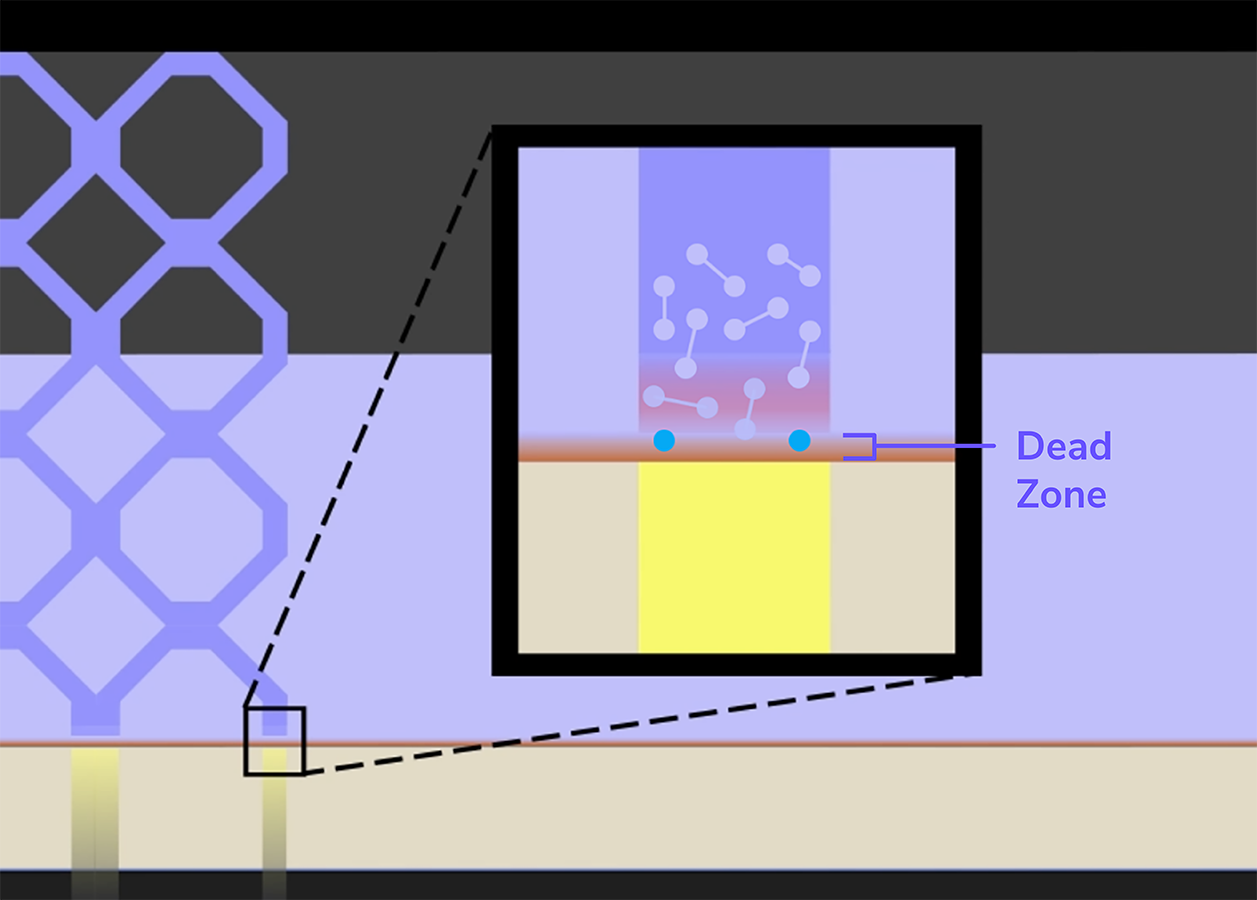
Carbon's proprietary CLIP technology enables DLS parts to avoid window contact due to the "continuous liquid interface" between the part and the window. The heart of the CLIP process is the **dead zone** - a thin oxygen-rich layer of resin above the window.
The photochemical process behind CLIP that cures liquid resin into solid parts uses ultraviolet light to polymerize (or solidify) the resin. That process is inhibited by the presence of oxygen, which is the key to the dead zone. DLS windows are highly engineered to be permeable to oxygen while also allowing UV light to shine through. A concentrated layer of oxygen sits just above the window that prevents resin from curing within the dead zone, hence its name.
The oxygen inhibits curing, which keeps the printed part from sticking to the window, and maintains space for liquid resin throughout the print, thus avoiding the slow and forceful peeling process that is inherent to many other resin-based printers.
**After Printing**
Once a part is printed, the DLS process continues to secondary curing. This comes in two forms:
::::VerticalSplit{layout="left"}
:::VerticalSplitItem
- 1-part resins have a secondary UV cure
- 2-part resins are baked in a forced-circulation oven. Heat sets off a secondary chemical reaction that gives parts their engineering mechanical properties.
:::
:::VerticalSplitItem

:::
::::
## Main Components and Definitions
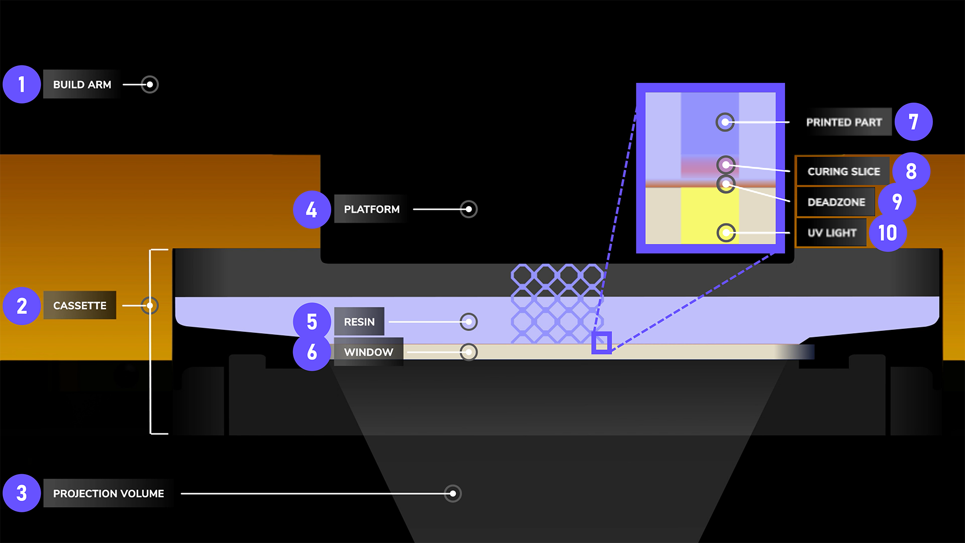
:::::::WorkflowBlock
::::::WorkflowBlockItem
:::::ExpandableHeading
**Build Arm**
::::VerticalSplit{layout="middle"}
:::VerticalSplitItem
The build arm holds the platform and moves it vertically during printing.
*Shown here without the platform attached on an M3 Printer.*
:::
:::VerticalSplitItem

:::
::::
:::::
::::::
::::::WorkflowBlockItem
:::::ExpandableHeading
**Cassette**
::::VerticalSplit{layout="middle"}
:::VerticalSplitItem
The cassette is a removable appliance that sits on the deck and holds liquid resin during printing.
*Shown here on an M3 Printer.*
:::
:::VerticalSplitItem

:::
::::
:::::
::::::
::::::WorkflowBlockItem
:::::ExpandableHeading
**Projection Volume**
The projection volume is an opening in the printer deck below an installed cassette.
Within the printer cavity below the deck resides the **light engine, **the digital light projector that shines UV light through the window during printing.
::::VerticalSplit{layout="middle"}
:::VerticalSplitItem
The **light engine's projector lens** can be viewed from above when the cassette is not installed.
*Shown here on an M3 Printer.*
:::
:::VerticalSplitItem

:::
::::
:::::
::::::
::::::WorkflowBlockItem
:::::ExpandableHeading
**Platform**
::::VerticalSplit{layout="middle"}
:::VerticalSplitItem
The platform is a removable appliacne with a flat surface upon which parts are printed.
It is held in palce by the build arm which moves vertically to build parts. When printing is completed, the platform is removed from the printer so that parts can be processed.
*Shown here on an M3 Printer.*
:::
:::VerticalSplitItem

:::
::::
:::::
::::::
::::::WorkflowBlockItem
:::::ExpandableHeading
**Resin**
::::VerticalSplit{layout="middle"}
:::VerticalSplitItem
The **liquid resin** is a photosensitive polymer that solidifies when exposed to UV light.
The cassette is filled with resin for printing.
*Shown here on an M3 Printer.*
:::
:::VerticalSplitItem

:::
::::
:::::
::::::
::::::WorkflowBlockItem
:::::ExpandableHeading
**Window**
::::VerticalSplit{layout="middle"}
:::VerticalSplitItem
The transparent **window** in the center of the cassette is permeable to both UV light and oxygen, creating a dead zone that unlocks the speed and quality of DLS printing.
During printing, light from the light engine shines through the window and cures liquid resin into a solid, while the oxygen inhibits curing in the dead zone.
*Shown here is an M3 Printer.*
:::
:::VerticalSplitItem

:::
::::
:::::
::::::
::::::WorkflowBlockItem
:::::ExpandableHeading
**Printed Part**
::::VerticalSplit{layout="middle"}
:::VerticalSplitItem
The printed part is the solidified resin that rises out of the liquid resin.
*Shown here on an M2 Printer.*
:::
:::VerticalSplitItem

:::
::::
:::::
::::::
::::WorkflowBlockItem
:::ExpandableHeading
**Curing Slice**
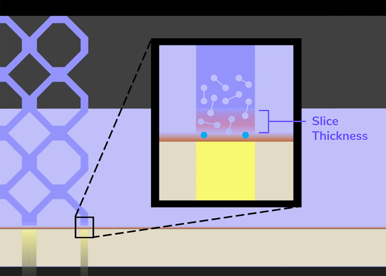
The slice that is currently curing is the **slice thickness** as set in the [Print Controls](docId\:N9rCrE4j391HMxwvP-udG) .
:::
::::
::::WorkflowBlockItem
:::ExpandableHeading
**Dead Zone**
The defining component of DLS printing, the dead zone is a thin oxygen-rich layer of resin above the window.
The oxygen inhibits curing, which keeps the painted part from sticking to the window and maintains space for liquid resin throughout the print.
*For scale, the dead zone is generally the thickness of a thin human hair. The actual thickness varies by resin and by the physics at play with part geometry.*
:::
::::
::::::WorkflowBlockItem
:::::ExpandableHeading
**UV Light**
::::VerticalSplit{layout="middle"}
:::VerticalSplitItem
The UV light shines through the cassette window, in the shape of the curing slice, from the light engine's projector in the printer cavity below.
*Shown here shining through a clear resin on an M1 Printer. *
:::
:::VerticalSplitItem

:::
::::
:::::
::::::
:::::::
## Isotropic Parts
The oxygen permeable window and dead zone provide another key benefit for DLS by creating isotropic parts. The dead zone has the highest concentration of oxygen to prevent curing, but the oxygen tapers off into the polymerization zones to create a **gradient of curing** across a slice.
::::VerticalSplit{layout="right"}
:::VerticalSplitItem

:::
:::VerticalSplitItem
- **More Polymerization**
Each new slice in this gradient zone bonds to its predecessors by connecting monomers across slices to form a uniform whole.
- **Less Polymerization**
Less cure closer to the window leaves more monomers free to attach to the next slice.
:::
::::
- **Dead Zone **
The oxygen-rich dead zone prevents curing just above the window. This keeps the part from sticking to the window and allows liquid resin to flow freely into the build area.
DLS production is a viable manufacturing option because parts are not weakened by the interface between individually cured layers: **DLS parts are isotropic**! Any printing orientation will yield consistent mechanical performance. Anisotropic parts by contrast are impacted by print orientation as parts are weaker along layers.
::::VerticalSplit{layout="middle"}
:::VerticalSplitItem

:::
:::VerticalSplitItem

:::
::::
::embed[]{url="https://player.vimeo.com/video/793551618?dnt=1"}
# DLS Printing Process
## Per Slice Printing
DLS printing is best understood by looking at what happens when each slice is printed. There are five core steps to print each slice. The video plays through 3 slices: one slice slowly and 2 more slices in real-time.
::embed[]{url="https://player.vimeo.com/video/786460318?dnt=1"}
*This is an example print of a rigid part. The exact timing of a printing slice and the force values will vary throughout the build and for each project. Z dimensions for pump height, slice thickness, and dead zone are exaggerated for visibility.*
**The following stages occur for each printed slice.**
1. Pump Up
2. Settle Up
3. Pump Down
4. Settle Down
5. Exposure
## Details per Slice Stage
:::::::WorkflowBlock
::::::WorkflowBlockItem
:::::ExpandableHeading
**Pump Up**
- Platform moves up to pump height
- Suction forces pull down on part (away from platform)
- Resin flows in below part
***
::::VerticalSplit{layout="left"}
:::VerticalSplitItem
**Pump Height**
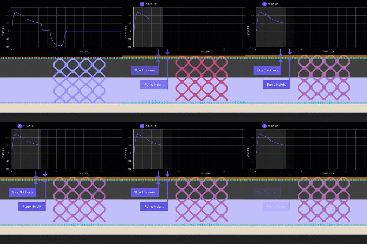
The platform moves up, away from the window, beyond the height needed to cure the next slice.
This extra distance, beyond the **slice thickness**, is the **pump height** and encourages resin flow to ensure there is adequate resin available to build the next slice.
:::
:::VerticalSplitItem
:::
::::
***
**Suction Forces**
Strong forces act upon the part as the platform rises, pulling the part away from the platform.
::::VerticalSplit{layout="left"}
:::VerticalSplitItem
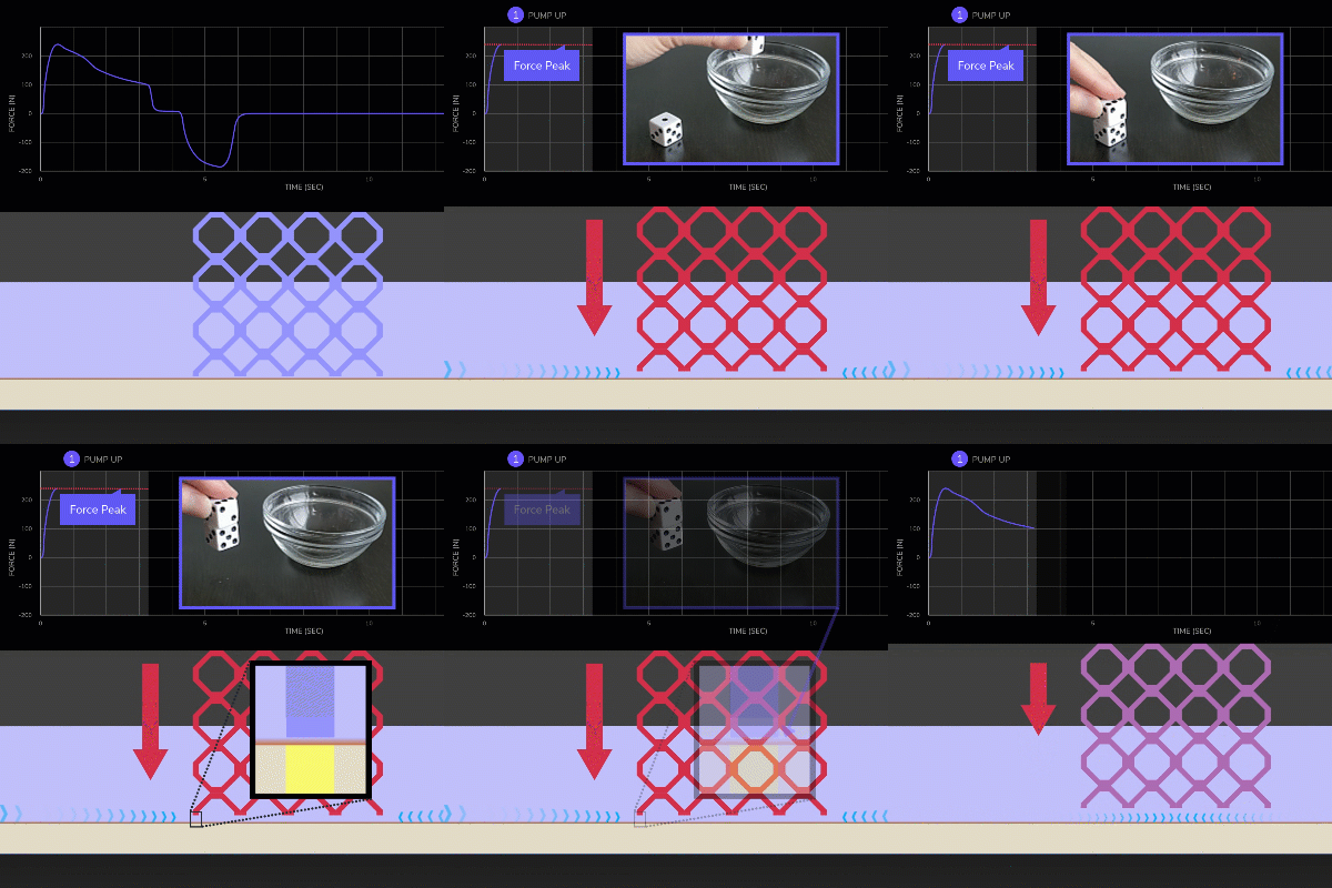
- The initial **force peak** is reached quickly as the part breaks the *surface tension* created from the thin layer of uncured resin in the dead zone between the part and the window.
- Forces decline after the peak but remain present due to the suction of lifting the part through a viscous liquid
:::
:::VerticalSplitItem
:::
::::
:::hint{type="info"}
Shown here with a **rigid** resin.
See below for how an **elastomer experiences stretching**.
:::
***
::::VerticalSplit{layout="left"}
:::VerticalSplitItem
**Force Peak on Elastomers**
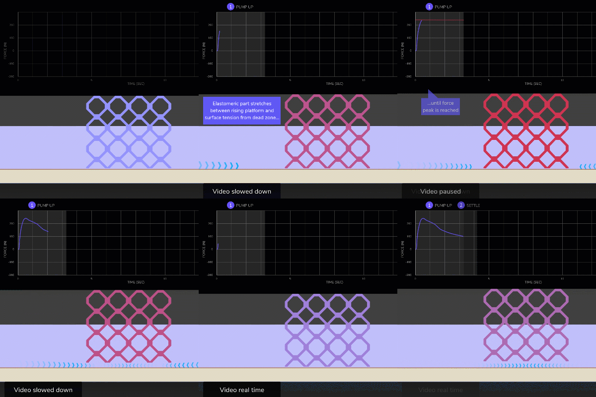
Because elastomeric resins are soft in their green state (the printed solid before secondary curing), the **parts experience stretching** as the platform rises, until surface tension is broken at the dead zone. This is especially true of lattices due to their pliability.
:::
:::VerticalSplitItem
:::
::::
:::hint{type="info"}
Note that **EPU 45** and **SIL 30** are elastomers that are **relatively stiffer** in their green state and therefore may experience less stretching than others, but still more than rigid resins.
:::
***
::::VerticalSplit{layout="left"}
:::VerticalSplitItem
**Resin Flow**
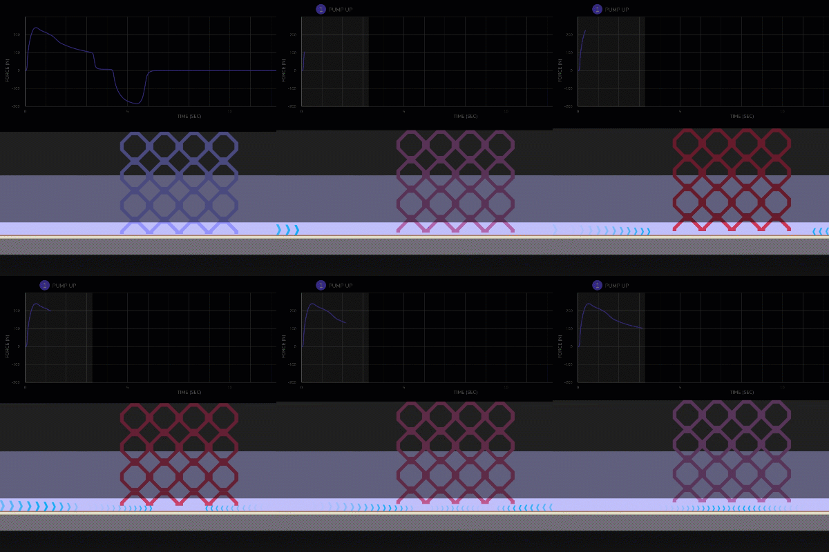
Due to the suction forces, **resin is pulled in** below the part to ensure adequate supply for the next slice.
:::
:::VerticalSplitItem
:::
::::
***
:::::
::::::
::::::WorkflowBlockItem
:::::ExpandableHeading
**Settle Up**
- Platform stays at pump height
- Forces stabilize
- Resin flow settles
***
::::VerticalSplit{layout="left"}
:::VerticalSplitItem
**Pump Height**
The **platform remains at the pump height** while forces and resin flow stabilize.
:::
:::VerticalSplitItem

:::
::::
***
::::VerticalSplit{layout="left"}
:::VerticalSplitItem
**Suction Forces**
Forces quickly lower to a stable level as the platform remains steady.
:::
:::VerticalSplitItem

:::
::::
***
::::VerticalSplit{layout="left"}
:::VerticalSplitItem
**Resin Flow**
Resin continues to flow inward below the part while the platform remains at the pump height. It is important that this settle phase lasts long enough for resin to reach the center of the part for the next slice.
:::
:::VerticalSplitItem

:::
::::
***
:::::
::::::
::::::WorkflowBlockItem
:::::ExpandableHeading
**Pump Down**
- Platform moves down to slice thickness
- Forces push part up into platform
- Resin flows out from below part
***
::::VerticalSplit{layout="left"}
:::VerticalSplitItem
**Slice Thickness**
The **platform moves down** to the slice thickness, just above the deadzone to prepare for the next slice.
:::
:::VerticalSplitItem

:::
::::
***
::::VerticalSplit{layout="left"}
:::VerticalSplitItem
**Forces**
Forces act upon the part in the negative direction, pushing it up into the platform as the part is pushed into a viscous liquid.
:::
:::VerticalSplitItem

:::
::::
***
::::VerticalSplit{layout="left"}
:::VerticalSplitItem
**Resin Flow**
As the part moves down, resin is pushed outwards.
:::
:::VerticalSplitItem

:::
::::
***
:::::
::::::
::::::WorkflowBlockItem
:::::ExpandableHeading
**Settle Down**
- Platform stays at slice thickness
- Forces stabilize
- Resin flow settles
***
::::VerticalSplit{layout="left"}
:::VerticalSplitItem
**Slice Thickness**
The **platform remains at the slice thickness** while forces and resin flow neutralize.
:::
:::VerticalSplitItem

:::
::::
***
::::VerticalSplit{layout="left"}
:::VerticalSplitItem
**Forces**
Forces stabilize as the platform remains steady.
:::
:::VerticalSplitItem

:::
::::
***
::::VerticalSplit{layout="left"}
:::VerticalSplitItem
**Resin Flow**
Resin continues to flow outward below the part while the platform remains at the slice thickness. It is important that this settle phase last long enough to stop resin flowing below the part
:::
:::VerticalSplitItem

:::
::::
***
:::::
::::::
::::WorkflowBlockItem
:::ExpandableHeading
**Exposure**
Resin cures, or solidifies, when exposed to UV light. The UV light is shining through the window in the shape needed to build the part. The slice thickness (as set in the print plan) is being cured, but the curing can be thought of more as a gradient of curing through this thickness.
1. The monomers, closest to the dead zone, do not connect to other monomers because the oxygen rich dead zone is preventing the curing process. These stray monomers remain ready to cure to the next slice, ensuring isotropy.
2. Most monomers connect within the slice to solidify.
3. Farthest from the oxygen rich dead zone, monomers connect to stray monomers from the previous slice. This connection between slices is why DLS printing yields isotropic parts.
::embed[]{url="https://vimeo.com/1059884568?dnt=1"}
:::
::::
:::::::
## Print Plan and Force Feedback
The software that drives a print and manages the 5 stages of printing each slice is called the **print plan**. Print plans determine how long each stage takes, drives the platform movement, and controls the exposure of UV light.
The type of printer you have dictates how the print plan determines each of these factors.
- Carbon's early generation printers (**M1, M2**) operate on a preset print plan based on the resin being printed.
- Later generation printers (**M3, M3 Max, L1**) have a built-in feature called **force feedback (FFB)** that allows the printer to adapt in real-time to suction forces and resin flow. This leads to more first print successes and fewer print defects overall.
**An FFB print plan adjusts as the printer measures forces.**
:::hint{type="info"}
Because **FFB printers** are adjusting in real-time, **print time estimates are approximate**. Estimates are conservative, so the actual print time will often result in faster prints than the estimate. Occasionally, the print time may adjust slightly longer. Either way, print time adjusts in real-time on the printer status page or touchscreen, so you can check on the print as it progresses.
:::
For both types of printer, it is possible to make advanced print plan adjustments to solve print defects or optimize for production. Learn how to use the [Print Plan Adjustments](docId\:NxUK0dltz_vemEAU0DIpN)** **feature in a separate course for each of the stages as described below.
| **Printing Step** | **M1, M2** | **Adjustable** | **M3, M3 Max, L1** | **Adjustable** |
| ----------------- | --------------------------------------------------------------------- | ----------------------------------------- | ----------------------------------------------------------------------------------------- | ---------------------------------- |
| 1 Pump Up | Speed and height for platform movement | **✓**
| Speed for platform movement
Platform height as a function of the peak force detected | **✓** |
| 2 Settle Up | Delay time | **X** | Delay as a function of how the force is stabilizing | **✓** |
| 3 Pump Down | Speed for platform movement | **✓** | Speed for platform movement | **✓** |
| 4 Settle Down | Delay time | **✓** | Delay as a function of how the force is stabilizing | **✓** |
| 5 Exposure | Exposure time
Base exposure
*(increases platform adhesion)* | **✓** | Base exposure
*(increases platform adhesion)* | **✓** |
:::hint{type="info"}
**Note about production validation across different printer types.**
If you have validated a production application on one type of printer and plan to switch to a different type, it is always advised to revalidate for production.
While newer generation printers with FFB have general advantages overall, that does not rule out the possibility of new defects arising or better print times in all cases. Additionally, M3 printers utilize a different cassette type and L1 printers have a different resolution, among other small variations in the hardware & software that can present as minor differences.
**When switching between M1/M2 ---> M3/M3 Max ---> L1, always revalidate a production application.**
:::
# DLS Dynamics
So far we have learned that Carbon's CLIP process allows DLS printers to avoid the slow and forceful peeling off the window process that is inherent to many other resin-based printers.
There are still factors at play affecting your parts that are inherent in any resin-based technology. Understanding these dynamics will help you get the best results from DLS printing.
## Suction
As the platform and part moves up through the viscous liquid resin, **suction forces** are created as resin is pulled into the void left in their wake.
- **PRO** **- **This is the primary mechanism for **pulling fresh resin in **below the part for printing the next slice.
- **CON** **- **Suction forces are **pulling your part away from the platform **which can lead to defects if not managed properly.
::::VerticalSplit{layout="left"}
:::VerticalSplitItem
**How forces are acting:**
- The initial **force peak** is reached quickly as the part breaks the *surface tension* created from the thin layer of uncured resin in the dead zone between the part and the window. *Shown here with a rigid resin.*
- Forces decline after the peak but remain present due to the suction of lifting the part through a viscous liquid.
:::
:::VerticalSplitItem

:::
::::
:::hint{type="info"}
Shown here with a **rigid** resin.
Refer to the [1 Pump Up](docId\:U7XYytjyDp3BvsYy2qKcU) stage decsription above for how an **elastomer experiences stretching**.
:::
***Managing Suction ***
Suction forces are pulling down on your part which can lead to **Under-Supported Overhang** or **Under-Adhesion **defects under certain unmitigated conditions.
***
::::VerticalSplit{layout="middle"}
:::VerticalSplitItem
**Problem** - [Under-Supported Overhang](docId\:NyU9Vh8WP7K9IGw0qOP8A)

Large overhangs are susceptible to suction forces and will be deflected away from the platofrm.
:::
:::VerticalSplitItem
**Solution**

- Supports can resist suction force on overhangs.
- Redesigns with gusset-like features can resist suction forces
:::
::::
***
::::VerticalSplit{layout="middle"}
:::VerticalSplitItem
**Problem** - [Under-Adhesion](docId\:DAbqNXb4KnG1eeiClRzqF)

Large cross sections (the surface area in a curing slice) are more susceptible to suction forces. When cross sections are larger later in the print, relative to the platform cross section, suction forces may pull the part off the platform.
:::
:::VerticalSplitItem
**Solution**

- Supports can resist suction forces.
- Reorientation of parts to place larger cross sections on the platform can overcome forces.
:::
::::
***
::::VerticalSplit{layout="middle"}
:::VerticalSplitItem
**Problem** - [Under-Adhesion](docId\:DAbqNXb4KnG1eeiClRzqF)

Asymmetrical parts, those that build at an angle away from their platform connection, may be susceptible to suction forces acting as torque on the part, pulling it off the platform.
:::
:::VerticalSplitItem
**Solution**

- Supports can resist suction forces on asymmetrical parts.
- Redesigns that place more cross section on the platform can overcome suction forces.
:::
::::
***
:::hint{type="info"}
Reference [DLS Design Guidelines](docId\:t94PR-A-C0pIhY6LJsWk7) for recommended overhangs per resin.
:::
## Heat
While curing is happening, **heat** is being generated from the chemical process of building polymers (the connection of monomers) that creates solids.
The timing and intensity of UV exposure is carefully controlled in the print plan to ensure parts do not overheat while curing. The software analyzes your part geometry and the print speed will be optimized to keep operating temperatures within an acceptable range.
::::VerticalSplit{layout="left"}
:::VerticalSplitItem
**1. **Larger cross sections, like those in solid parts, generate more heat because more resin is curing. The print plan will **slow down** for these geometries while the heat dissipates into the surrounding liquid resin.
**2. **Designs that have been optimized with smaller cross sections generate less heat and can** print faster**. As a bonus, parts like this use **less material** which also helps lower cost.
:::
:::VerticalSplitItem

:::
::::
:::hint{type="info"}
M3, M3 Max, and L1 printers may be less affected by heat.
:::
:::hint{type="info"}
**Part height also affects print speed, more significantly than heat. **
Learn more about [reducing printing time](docId\:DoBa4qKKoXpi-52yw3nCr) and other cost factors with **Orientation & Supports guidelines**.
:::
## Shrinkage
During printing and post-processing, parts undergo a physio-chemical process that can cause the size of the printed part to be smaller from the nominal dimensions in the 3D model.
There are three causes of shrinkage in DLS production.
- Cooling (\~0.3%)
- Solidification (\~0.3%)
- Mass Loss (0.3% or higher)
*Affects 2-part resins only*
***
::::VerticalSplit{layout="middle"}
:::VerticalSplitItem
**Cooling (\~0.3%)**
Like all manufacturing processes that involve heat, material shrink is a factor when parts cool down.
- Heat is generated during curing
- Heat dissipates into the surrounding liquid resin
- As the solidified resin cools, molecules slow down and take up less space, causing the part to shrink*Also known as thermal contraction.*
:::
:::VerticalSplitItem

:::
::::
***
::::VerticalSplit{layout="middle"}
:::VerticalSplitItem
**Solidification (\~0.3%)**
Solidification (also called curing or polymerization) refers to single molecules of monomers linking together into a larger **polymer network **that forms your part.
When resin solidifies, it shrinks as molecules are pulled closely together.
1. **Monomer** molecules float freely in the liquid resin before they are cured
2. UV light triggers chemical reactions that cause those molecules to link together into chains of polymers. This process** pulls molecules closer together, which causes shrinkage.**
1. **Some monomers do not bind** to the network and remain unconnected in the solidified part.
:::
:::VerticalSplitItem

:::
::::
***
::::VerticalSplit{layout="middle"}
:::VerticalSplitItem
**Mass Loss (0.3% or higher)**
Mass loss refers to unlinked monomers escaping from the part during secondary thermal curing (also known as baking). Monomers close to the surface move out of the part as the part is heated. When these molecules are lost, the part shrinks. **Only 2-part resins are affected** by mass loss as only those resins are baked after printing.
*(1-part resins' secondary curing is done with UV light)*
Mass loss **increases for thin walled parts** because more monomers in the part interior are close to the part surface.
1. Parts with a high ratio of surface area to volume expose more monomers to the part surface, causing more shrinkage.
2. Thicker walled parts expose fewer monomers to the part surface and experience less mass loss during baking.
:::
:::VerticalSplitItem

:::
::::
***
***Managing Shrinkage***
**Carbon software** does most of the heavy lifting to compensate for shrinkage with **correction scaling**.
- Based on the resin selected, the software subtly adjusts the scale of your imported model to compensate for the effects of cooling and solidification shrinkage.
- Additionally, when a 2-part resin\* is selected, the software analyzes your part geometry and further adjusts the scale of the part to compensate for mass loss, based on the average wall thickness.
:::hint{type="info"}
\*Only a subset of 2-part resins receive this adjustment. The remaining 2-part resins are are less susceptible to mass loss and only receive a static scale adjustment like the 1-part resins.
:::
You can adjust the factors used for [correction scaling](docId:4Z6MFha_0Lh3vOpPv9Jmn) in the software if desired.
There are more actions you can take to additionally improve shrinkage.
***
::::VerticalSplit{layout="middle"}
:::VerticalSplitItem
**For Cooling Shrinkage**
- Avoid sudden changes in cross section so that heating and cooling changes gradually during printing.
- Utilize smaller cross sections so less heat is generated.
:::
:::VerticalSplitItem

:::
::::
***
::::VerticalSplit{layout="middle"}
:::VerticalSplitItem
**For Mass Loss Shrinkage**
- **Design** - Maintain uniform wall thicknesses for equal mass loss throughout the part.
- This example has very thin walls at the inner grid pattern but a wider frame. The grid is losing more mass because of the thin walls, which pulls the thicker frame inwards to create the bowing edges.
- **Process** - Utilize baking strategies that maintain uniform heat around the part to equalize mass loss.
*Reference **Advanced Thermal Curing** training for more information.*
- Raise parts on a mesh
- Hang parts
- Utilize salt baking
- Utilize baking fixtures
:::
:::VerticalSplitItem

:::
::::
***
## Unvented Volumes
::::VerticalSplit{layout="middle"}
:::VerticalSplitItem
Unvented volumes trap resin in a pressure vacuum during printing which can cause print defects.
:::
:::VerticalSplitItem

:::
::::
**Possible defects** from an unvented volume:
::::LinkArray
:::LinkArrayItem{headerType="IMAGE" headerImage="https://api.archbee.com/api/optimize/dptYqcTHPbVZhe3zuNg4v-4mgbgODEtgs7k2eJ_EcBV-20250102-002645.png"}
[Blow Out](docId\:ygAbVQOmuTwYuvDOvnBfN)
:::
:::LinkArrayItem{headerType="IMAGE" headerImage="https://api.archbee.com/api/optimize/dptYqcTHPbVZhe3zuNg4v-7GbQP6v8GfPdZx2ZzfMyu-20250225-022037.gif"}
[Fringing](docId\:UP-Tsq77rAZxLvuEVCVmq)
:::
:::LinkArrayItem{headerType="IMAGE" headerImage="https://api.archbee.com/api/optimize/dptYqcTHPbVZhe3zuNg4v-t0GDLIR-_HTH_V4u4TV4e-20250102-010136.png"}
[Vacuum Line](docId\:uIA3VrtjsNOqvyXwL8VxS)
:::
::::
Related defects that unvented volumes can exacerbate:
::::LinkArray
:::LinkArrayItem{headerType="IMAGE" headerImage="https://api.archbee.com/api/optimize/dptYqcTHPbVZhe3zuNg4v-CZDwh_lptvzK6jz9vmlTm-20250102-004959.png"}
[Resin Starvation](docId:3EIqqQqCGKwU6QNgdR5Ox)
(by trapping resin)
:::
:::LinkArrayItem{headerType="IMAGE" headerImage="https://api.archbee.com/api/optimize/dptYqcTHPbVZhe3zuNg4v-xCXwS20-vkvjurjQUk7EB-20250222-013933.png"}
[Under-Adhesion](docId\:DAbqNXb4KnG1eeiClRzqF)
(from suction forces)
:::
::::
:::hint{type="info"}
Carbon software will provide warnings of unvented volumes in a print project. Reference [Project Analysis](docId\:gfR-GoC-Irq_L9_KanC-X) for more information.
:::
***Managing Unvented Volumes***
The solution for unvented volumes is to **provide venting** to equalize the pressure differential. Venting should be provided** at, or near, the platform**.
::::VerticalSplit{layout="middle"}
:::VerticalSplitItem

:::
:::VerticalSplitItem

:::
::::
:::hint{type="info"}
Reference [DLS Design Guidelines](docId\:t94PR-A-C0pIhY6LJsWk7) for vent hole guidance.
:::