---
title: Dreve FotoDent IBT
slug: materials/dreve-fotodent-ibt
docTags:
createdAt: 2024-07-15T15:39:45.524Z
---
# Overview
::::VerticalSplit{layout="middle"}
:::VerticalSplitItem
**Dreve FotoDent® IBT for Carbon printers** is now available to produce indirect bonding trays. The material is a clear, biocompatible resin and is ideal for fast production.
This guide will cover digital pre-processing of your IBT devices to properly prepare them for printing with FotoDent® IBT for Carbon printers.
:::
:::VerticalSplitItem

:::
::::
:::hint{type="info"}
This resin is not currently compatible with the [AO Polishing Cassette](docId\:iFFh3q8-WLk-LIqr87bd5).
:::
## Resource Links
::::LinkArray
:::LinkArrayItem{headerType="IMAGE" headerImage="https://api.archbee.com/api/optimize/uXbZOKjJTGpPhjapQ8fvM-IOQIJkNnkbUAw9Q-ap1FV-20241115-235121.jpg"}
**[About the Material](https://www.carbon3d.com/materials/fotodent-ibt)**
:::
:::LinkArrayItem{headerType="IMAGE" headerImage="https://api.archbee.com/api/optimize/3CesIL2dYMCHPZvRjp8S0/cJAKqDDnRUAeJAXNRThMm-20251016-221334.png"}
**[Manufacturer Instructions for Use](https://innovation-meditech.de/fileadmin/medienablage/Innovation_Meditech/Downloads/FotoDent-Downloads/Gebrauchsinformationen/INST_FotoDent_IBT_DE_GB_FR_ES_IT.pdf?expired=1728002844)**
:::
:::LinkArrayItem{headerType="IMAGE" headerImage="https://api.archbee.com/api/optimize/3CesIL2dYMCHPZvRjp8S0/1r3fpdvMUMFVZGfey2Tjn-20251016-221405.jpg"}
**[Safety Data Sheet](https://innovation-meditech.de/en/fotodentr)**
*Scroll to bottom of page and select Safety data sheets*
:::
::::
## Protocol
This downloadable handout provides important usage information, including instructions about storage and post-processing. Print it out and bring it into the lab!
::File{src="https://api.archbee.com/api/presign/uXbZOKjJTGpPhjapQ8fvM-hnfuYy29ncDLgqTLIX5EP-20241004-162526.pdf" label="Dreve FotoDent IBT Protocol v01.01.pdf"}
## Dental Post-Processing Grids
::::VerticalSplit{layout="right"}
:::VerticalSplitItem
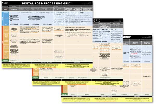
One of our most popular downloads! This table provides washing and curing instructions for all supported dental resins.
Print it and use it in the lab as a quick reference.
:::
:::VerticalSplitItem
:::
::::
::::VerticalSplit{layout="left"}
:::VerticalSplitItem
**English**
:::
:::VerticalSplitItem
::File{src="https://api.archbee.com/api/presign/3CesIL2dYMCHPZvRjp8S0/vQ2WsRger2d-CoLrn-m5f_dental-post-processing-grids-v0501.pdf" label="Dental-Post-Processing-Grids_v0501.pdf"}
:::
::::
::::VerticalSplit{layout="left"}
:::VerticalSplitItem
**German/Deutsch**
:::
:::VerticalSplitItem
::File{src="https://api.archbee.com/api/presign/uXbZOKjJTGpPhjapQ8fvM-seBSLAiWUzNDRI1GCLlop-20241125-214312.pdf" label="ZAHNÄRZTLICHES NACHBEARBEITUNGSGITTER v03.71 DE Deutsch.pdf"}
:::
::::
::::VerticalSplit{layout="left"}
:::VerticalSplitItem
**Spanish/Español**
:::
:::VerticalSplitItem
::File{src="https://api.archbee.com/api/presign/uXbZOKjJTGpPhjapQ8fvM-2i0UhzOfuA4aYJFusL1v2-20241203-180542.pdf" label="Rejilla de Posprocesamiento Dental v03.71 ES Espanol Spanish.pdf"}
:::
::::
# Design Recommendations
## Flat Occlusal Plane
**Carbon strongly recommends creating devices with flat occlusal planes**. This maximizes yield while minimizing printing and post-processing times.
::::VerticalSplit{layout="middle"}
:::VerticalSplitItem
1. **Flat and featureless occlusal plane**
- Creates a strong tray
- Minimizes part failure due to adhesion issues
2. **Minimum wall thickness of 1 mm** for optimal print outcomes
- Prevents breaking
3. **Minimize part height**
- Conserves resin
- Minimizes print time
4. **Parts should be solid**
- Avoids potential venting issues during printing that can lead to failure
:::
:::VerticalSplitItem

:::
::::
## Conformal Occlusal Plane
If it is not possible to design a device with a flat occlusal plane, then conformal occlusal planes may be used.
::::VerticalSplit{layout="middle"}
:::VerticalSplitItem
Be aware that conformal occlusal plane devices have the following effects:
- Part must be printed at angle relative to platform
- Support structures are required
- 2-3x increase in print time relative to flat occlusal plane
- Post-processing time increases due to support removal
1. **Minimum wall thickness of 1 mm** for optimal print outcomes
- Prevents breaking
:::
:::VerticalSplitItem

:::
::::
# General Orientation & Support Information
## Hide the Platform
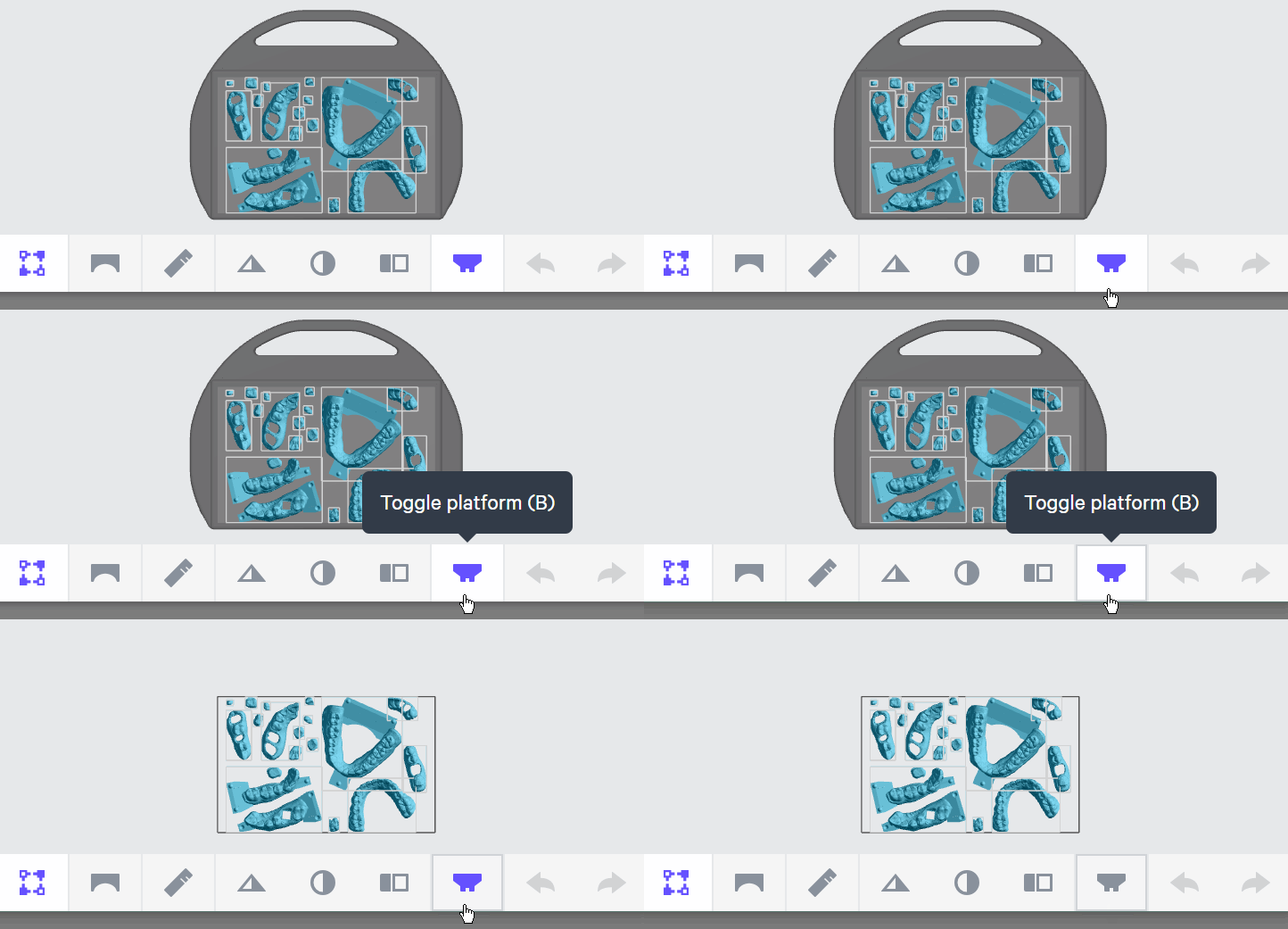
Use **Toggle platform** (or press **B**) to hide the platform before orienting parts. This will make it easier to see overhangs and place supports.
## Use Fence tools to create supports
::::VerticalSplit{layout="middle"}
:::VerticalSplitItem
### Fence tool
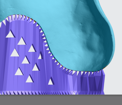
- [Fence supports](docId\:VUbpoAitbLM11aM9-qJ1p) are manually placed by the user and are best suited on **linear overhangs **or smaller areas.
- Fences provide stability while leaving smaller nubs than the default Bars option.
::Image[]{src="https://res.cloudinary.com/carbon3d/image/upload/v1741914724/Education/Materials/dental/__General_Use/standard-support-menu-fence.png" size="50" width="214" height="77" position="flex-start" showCaption="false"}
:::
:::VerticalSplitItem
:::
::::
:::hint{type="info"}
Review [Supports](docId\:VUbpoAitbLM11aM9-qJ1p) in [Printer UI](docId\:oId4ZNZtZYeltTPVJ984a) course for more information.
:::
# Orient & Support Flat Occlusal Planes
Proper orientation of indirect bonding trays is critical.
- Maximizes yield by minimizing print defects.
- Eliminates the need for supports and the accompanying labor and resin costs.
- Achieves the required accuracy and surface quality.
:::hint{type="success"}
**All indirect bonding trays should be oriented to be flat against the build platform**.
:::

## Orienting
::::VerticalSplit{layout="middle"}
:::VerticalSplitItem
Use **Snap to Platform **to ensure the flat base is aligned with the platform.
1. Click on **Orient** in the main bar in the printer software.
2. Select the part to be oriented.
3. Under Snap to Platform click the **Select Surface button**.
4. **Click anywhere on the flat base of the tray part**. The printer software will **automatically rotate the part base to be parallel with the platform**.
:::
:::VerticalSplitItem

:::
::::
:::hint{type="success"}
Use Snap to Platform on all parts to ensure the part base is flat against the platform. Even a small anlgle between the part and the platform may result in a failed print.
:::
### Z Rotation of Tray Parts
::::VerticalSplit{layout="middle"}
:::VerticalSplitItem
As long as the base of the part is snapped to the platform,** you have freedom to rotate the part in the Z axis to suit your needs.**
:::
:::VerticalSplitItem

:::
::::
## Supporting
Indirect bonding tray parts with a flat occlusal plane do not require supports because they print directly on the platform.
## Properly Oriented And Supported IBT Part
- All indirect bonding trays should be oriented to be flat against the build platform.
- Any orientation is acceptable.

# Orient & Support Conformal Occlusal Planes
## Orienting
IBTs with conformal occlusal planes should be oriented
- 45 degree angle with anterior teeth furthest from the platform
- Intaglio surface facing the platform

::::VerticalSplit{layout="middle"}
:::VerticalSplitItem
Perform an initial orientation of both bases so that they are roughly parallel with the platform.
1. Click on **Orient** in the main bar in the printer software.
2. Orient each base so that the intaglio surface is facing the platform.
3. Adjust the trays so that they are **mostly parallel with the platform**.
- We recommend typing values into the XYZ axis fields. Changing orientation with the mouse or Snap to Platform function is more challenging.
4. Position the camera so you are looking straight down on the platform:
1. Push the **Reset camera icon** in the lower left corner of the screen to return to the default view.
2. Push **▲ to look straight down** at platform.
5. Make sure that the **posterior region of the tray is facing the lower portion of the screen**.
:::
:::VerticalSplitItem

:::
::::
Now perform the final orientation. Because indirect bonding trays with conformal occlusal planes are organic surfaces with no well defined flat areas, Carbon does not recommend using Snap To Platform. It is much easier to enter values directly into the **Orient** fields.
::::VerticalSplit{layout="middle"}
:::VerticalSplitItem
1. Click on the part to select it.
2. Enter a value of **45 degrees** into the X Axis field.
3. The **posterior** of the part should be touching the platform.
:::
:::VerticalSplitItem

:::
::::
### Z Rotation of Tray Parts
::::VerticalSplit{layout="middle"}
:::VerticalSplitItem
**You have freedom to rotate the part in the Z axis to suit your needs.**
:::
:::VerticalSplitItem

:::
::::
## Supporting
Carbon recommends using **fences **to support IBT devies. They are easy to remove and do not increase the footprint of the part, enabling more parts to be fit onto the build platform.
::::VerticalSplit{layout="middle"}
:::VerticalSplitItem
1. Click **Support** in the main bar in the printer software.
2. Under Position, select **Above Platform** to create room between the platform and the part.
3. Skip **Auto Support Method** as this mode is not recommended.
4. Click **Manually Add** to enter the Support editing interface.
:::
:::VerticalSplitItem

:::
::::
### Add Fences
You will now see the support editing view. Support the entire perimeter of the intaglio walls.
::::VerticalSplit{layout="middle"}
:::VerticalSplitItem

:::
:::VerticalSplitItem
1. Click **Toggle Platform button** in the lower tool bar to hide the platform. This will enable better visibility during fence creation.
2. Click the **fence icon** in the top menu bar.
3. Click a **series of points** on the base to define the fence.
- Use **Overhang Detection** to find areas that need support.
- Carbon recommends making a series of small fences rather than making a single continuous fence to give greater flexibility to reposition points.
4. Click **ESC key** and then hold down **E key** to reposition points.
5. Click **Generate** to create the fence geometry. This may take a few minutes.
:::
::::
:::hint{type="info"}
See [Fences](https://app.archbee.com/docs/u0_rn6-bXClBlKIlma4jh/VUbpoAitbLM11aM9-qJ1p#x6M_b) in Printer UI for more information about the fence workflow.
:::
## Properly Oriented And Supported IBT Part
- 45 degree orientation with anterior teeth facing away from platform.
- Intaglio surface facing platform.
- Any Z axis-rotation is acceptable.

# Nesting

::::VerticalSplit{layout="right"}
:::VerticalSplitItem
1. Select the **Layout tab**** (Shift + L)** in the top menu bar.
2. Under **Auto Layout,** select **Gen2.**
- Gen2 usually gives the most effecient packing for dental devices.
3. Enter at least **1 mm** in **Padding.**
- Models require a minimum of 1 mm of space between them.
4. Leave **Optimize starting rotation** unchecked.
- This leaves your parts in their previous orientations.
5. Leave **Allowed rotations** at the default setting.
- This gives the software maximum flexibility to fit the most possible parts on the build platform.
6. Press the **Auto Layout** button to arrange your parts.
:::
:::VerticalSplitItem

:::
::::
If necessary, nesting can be changed manually:
- Click and drag parts to adjust their position.
- Modify Z rotation by using the **Spin **tool or manual rotations under the **Orient tab** **(Shift + O).**
- Use the **Part List tab **as needed to more easily select models and focus on them.
# Print Preparation
## Print Controls
Click **Print Controls** or **Shift + P** in the top menu bar.

### Slicing
Slice Thickness should be **Standard (100 µ)**.
:::hint{type="warning"}
Reducing the slice thickness by choosing the Fine (50 µ) or Super-fine (25 µ) settings will increase print time and may reduce part quality and accuracy.
:::
## Project Analysis
1. Select the **Project Analysis** tab.
2. Click **Start Analysis** and wait for the processing to complete.
1. Note the required resin volume and print time.
3. Click **Add to Queue.**

# Manufacturer Instructions for Use
::File{src="https://innovation-meditech.de/fileadmin/medienablage/Innovation_Meditech/Downloads/FotoDent-Downloads/Gebrauchsinformationen/INST_FotoDent_IBT_DE_GB_FR_ES_IT.pdf?expired=1728061575" label="https://innovation-meditech.de/fileadmin/medienablage/Innovation_Meditech/Downloads/FotoDent-Downloads/Gebrauchsinformationen/INST_FotoDent_IBT_DE_GB_FR_ES_IT.pdf?expired=1728061575"}
# Questions & Support
**For questions about the resin properties, printing, washing or curing your parts, please contact the Dreve technical team:**
- Email: support-fotodent\@dreve.com
- Phone: 952-358-3526
For questions about your **Carbon printer** or **Carbon software settings** used for this resin, please [contact Carbon](https://learn.carbon3d.com/carbon-support):
- Email: [support@carbon3d.com](mailto\:support@carbon3d.com)
- Phone:
- **U.S. and Canada** 1-650-285-6307 option 2
- **Germany** +49 6102 5790849
- **UK **+44 (0) 2082 647484
- Printer UI: On the dashboard, select the **Prints** tab. **Select one of the printed projects.** Click **Request Help** in the lower right corner.
::Image[]{src="https://api.archbee.com/api/optimize/3CesIL2dYMCHPZvRjp8S0/YY6yCChSIB8SevmBwY76W_request-help-01.png" size="70" width="6541" height="3371" position="flex-start" alt="Location of button in the printer software" showCaption="false"}